Automatic point grinding device

A technology of equipment and power device, applied in the field of automatic research equipment, can solve the problems of low degree of automation, cumbersome operation, low efficiency, etc., and achieve the effect of solving cumbersome evaluation operation

Active Publication Date: 2020-05-01
WUHU INST OF TECH
View PDF18 Cites 0 Cited by
  • Summary
  • Abstract
  • Description
  • Claims
  • Application Information

AI Technical Summary

Problems solved by technology

[0006] In view of this, the object of the present invention is to propose an automatic research point equipment to solve a series of problems such as cumbersome operation, low efficiency, low degree of automation, and low safety when performing automatic research point operations in large-scale machine tools or machine manufacturing processes. , so that the operation of the research point is simple, safe and reliable

Method used


Image

  • Automatic point grinding device
  • Automatic point grinding device

Examples


Embodiment 1

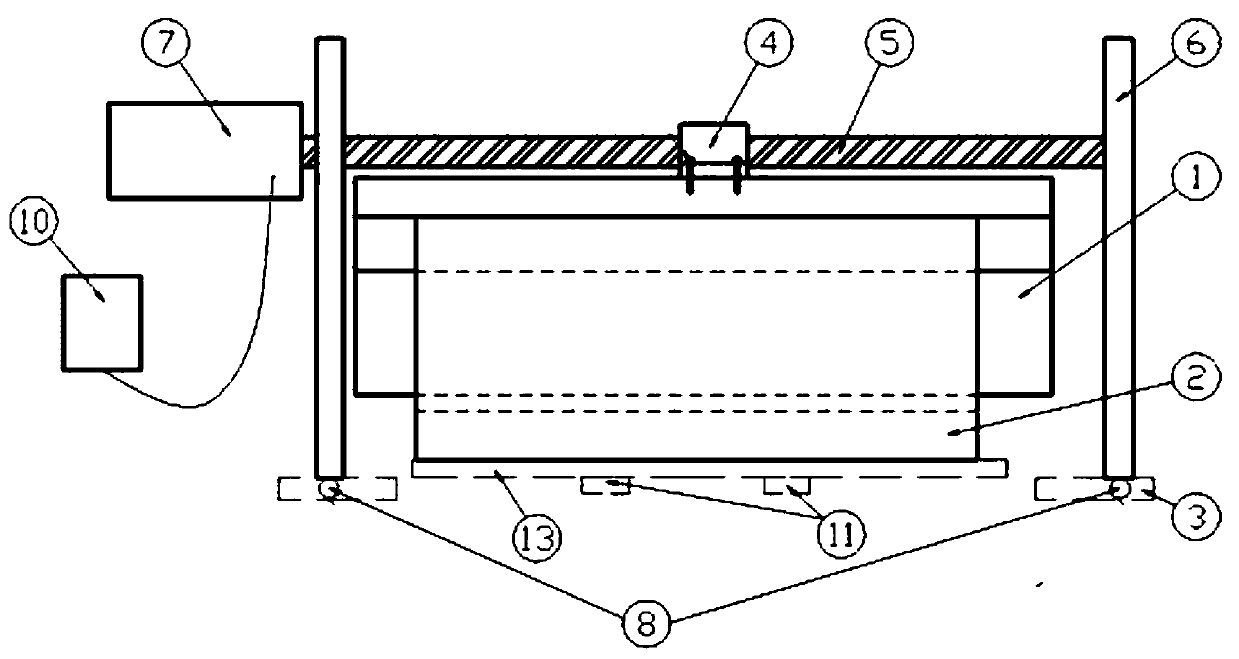
[0023] As shown in the figure, a kind of automated research equipment, the provided automated research equipment includes a base 3 installed on the ground, the bottom of the base 3 is provided with a pressure sensor 8, the pressure sensor 8 detects the base 3 and The total weight of the equipment carried by it can be obtained by subtracting the self-weight of the equipment to obtain the load of the external force. The automatic research point equipment also includes a support frame 6 arranged on the base 3, a ball screw pair arranged on the support frame 6, a power unit 7 arranged on the support frame 6, an electric motor set on the support frame 6 The control system 10, the workbench 13 arranged on the ground and several groups of jacks 11 arranged at the bottom of the workbench 13.

[0024] Described base 3 is four groups, and four groups of bases 3 are distributed on the four corners of a rectangular figure on the ground, and described support frame 6 is n shape, and each s...

Embodiment 2

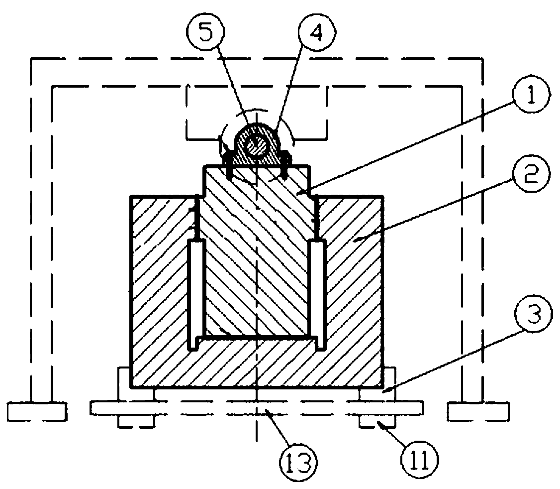
[0030] Further, according to different workpiece structures, research point requirements and factory production needs, the worktable 13 of the research point equipment in this case can be transformed into a 360° indexable and fixed movable workbench, in order to achieve 360° rotation , the workbench 13 includes a base, a top plate arranged above the base, and a rotating rod arranged between the top board and the base, the lower surface of the top plate is provided with a counterbore for installation, the lower end of the rotating rod is fixedly connected with the base, and the rotating rod The upper end is inserted into the installation sink of the top plate. The rotating rod is perpendicular to the horizontal plane, and the axis of the mounting counterbore passes through the center of gravity of the top plate.

[0031] Realize the automatic following of the direction during the grinding point, no need to consider the installation direction between the first workpiece 1 and th...


PUM


Abstract

The invention discloses an automatic point grinding device, and belongs to the technical field of machine tool machining. The automatic point grinding device aims to solve a series of problems that inthe large machine tool or machine manufacturing process, automatic point grinding operation is complex, efficiency is low, the automation degree is low, and safety is low. The automatic point grinding equipment comprises a base, a pressure sensor, supporting frames, a ball screw pair, a power device, an electrical control system, a workbench and a plurality of sets of jacks, wherein the base, thepressure sensor, the supporting frames, the ball screw pair, the power device, the electrical control system, the workbench and the jacks are installed on the ground; the electrical control system iselectrically connected with the power device, the jacks and the pressure sensor. The ball screw pair comprises a lead screw and a nut arranged on the lead screw; the two ends of the lead screw are fixed to the two supporting frames through bearings; the power device is connected with the lead screw and controls the lead screw to rotate and stop; an external thread is arranged on the surface of the lead screw; an internal thread matched with the external thread is arranged on the nut; and a connecting hole is further formed in the nut. With the adoption of the device, the point grinding operation is simple, easy to implement, safe and reliable.

Description

technical field [0001] The invention belongs to the technical field of machine tool processing, and specifically relates to an automatic research equipment. Background technique [0002] Scraping refers to the fitter operation that uses a scraper to scrape off trace metals on the surface of the processed workpiece to improve the accuracy of the surface shape and improve the contact between the mating surfaces. Scraping is an important method for final finishing of various profiles in mechanical manufacturing and repair, such as machine tool guide rail surfaces, connecting surfaces, bearing bushes, and mating spherical surfaces. Scraping improves the matching accuracy between interactive matching parts and improves the oil storage conditions. During the assembly process of machine tools, the sliding grinding method is used before scraping on both the sliding joint surface and the fixed joint surface. Apply paint to make the two mating surfaces slide reciprocally for a short ...

Claims


Application Information

Patent Timeline
IPC IPC(8): G01M5/00G01N3/00G01N3/02
CPCG01M5/0075G01N3/00G01N3/02
Inventor 张旭马文武李海洋李垠杨树林
Owner WUHU INST OF TECH
Why Eureka
Try Eureka