
Insulator detection mechanism and method

An insulator detection and insulator technology, which is applied in the direction of applying stable tension/pressure to test the strength of materials, can solve the problems of national economic losses, losses, threats to the continuous and reliable operation of the power system, and achieve uniform heating and uniform cooling effect.

Active Publication Date: 2020-05-01
HENAN RUIHENG ELECTRICITY CO LTD
View PDF7 Cites 3 Cited by
  • Summary
  • Abstract
  • Description
  • Claims
  • Application Information

AI Technical Summary

Problems solved by technology

The insulator strings of transmission lines are all running in parallel. Any problem with a string of insulators will cause the failure of the transmission line, or even a long-term power outage, which threatens the continuous and reliable operation of the power system and brings many problems to people's daily life. Inconvenience, causing certain losses to the national economy
When any one of the insulators in operation has a mechanical failure, it may cause a serious accident of string drop, which may cause immeasurable losses
[0003] Insulators are generally made of silica gel or ceramics. After the insulator is produced, it is necessary to perform a tensile test on the insulator to test its mechanical properties. Since the insulator has been exposed to the atmosphere for a long time, it has been exposed to cold and heat fusion, sun and rain for a long time during its operation. However, the existing insulator detection equipment can only detect the mechanical properties of insulators at room temperature, which brings a lot of inconvenience to the detection of insulators.

Method used


Image

  • Insulator detection mechanism and method
  • Insulator detection mechanism and method
  • Insulator detection mechanism and method

Examples


Embodiment Construction

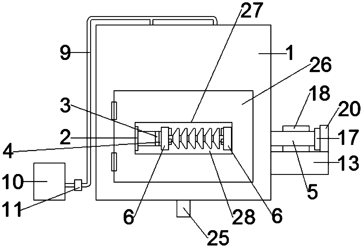
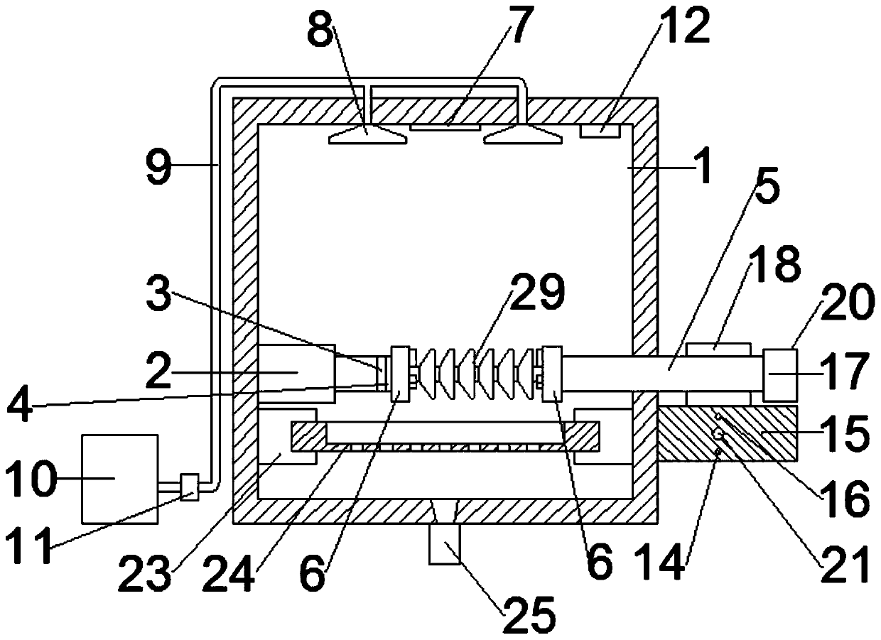
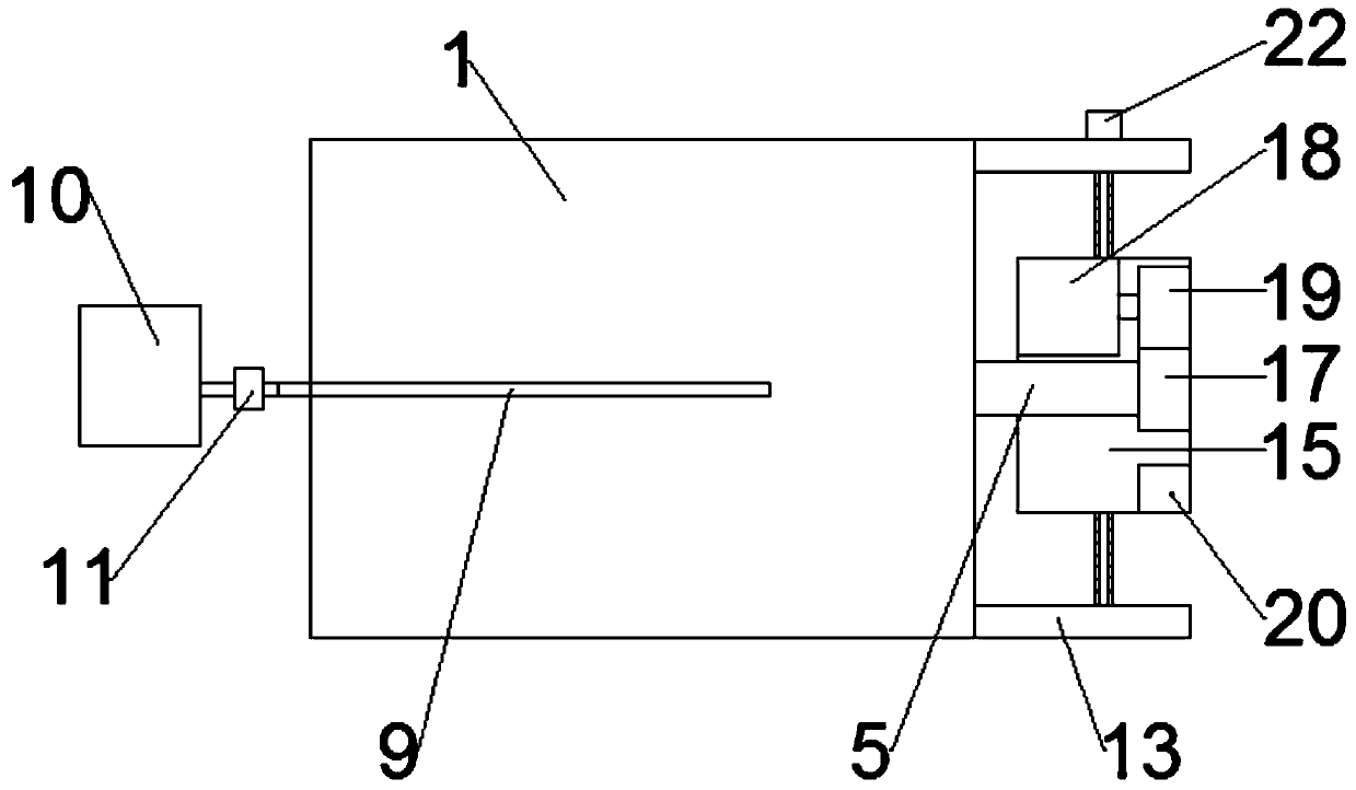
[0032] Such as Figure 1 to Figure 8 As shown, an insulator detection mechanism includes a detection box 1, a hydraulic cylinder 2 with a telescopic rod extending to the right is fixedly installed on the inner side of the left side wall of the detection box 1, and the right end of the telescopic rod of the hydraulic cylinder 2 is rotated and installed There is a fixed seat 3, the axis of rotation of the fixed seat 3 extends laterally, and the right side of the fixed seat 3 is fixedly equipped with a tension sensor 4; The axis of rotation of the shaft 5 coincides with the axis of rotation of the fixed seat 3, and the right end of the tension sensor 4 and the left end of the horizontal shaft 5 are respectively fixed with insulator fixtures; A driving device for rotating the shaft 5; a heating device is provided in the detection box 1, and a cooling device is also provided in the detection box 1.

[0033] Specifically, the insulator fixture is a three-jaw chuck 6, and the axes o...


PUM


Abstract

The invention relates to the technical field of insulator detection, and particularly relates to an insulator detection mechanism and method. A fixed seat is rotationally mounted at the right end of atelescopic rod of a hydraulic cylinder, wherein a tension sensor is fixedly mounted on the right side of the fixed seat; a transverse shaft is rotationally mounted on the right side wall of a detection box; insulator clamps are fixedly mounted at the right end of the tension sensor and the left end of the transverse shaft correspondingly; a heating device is arranged in the detection box; and a cooling device is further arranged in the detection box. According to the insulator detection mechanism and method, a steel cap or a steel foot of an insulator is clamped through a three-jaw chuck, then the hydraulic cylinder contracts to carry out stretching detection on the insulator, the tension sensor is used for detecting the tension when the insulator is broken, or the insulator is heated through a heating lamp, then a spray head sprays cold water to cool the insulator, then the hydraulic cylinder contracts to carry out stretching detection on the insulator, the tension sensor is used fordetecting the tension when the insulator subjected to cold and hot fusion is broken, and the insulator can be detected in various environments.

Description

technical field [0001] The invention relates to the technical field of insulator detection, in particular to an insulator detection mechanism and a detection method. Background technique [0002] Insulators are the most widely used devices in power systems. Compared with other power equipment and devices, although insulators are simple in result and relatively low in cost, their importance is no less than any other equipment and devices. The insulator strings of transmission lines are all running in parallel. Any problem with a string of insulators will cause the failure of the transmission line, or even a long-term power outage, which threatens the continuous and reliable operation of the power system and brings many problems to people's daily life. Inconvenience, causing certain losses to the national economy. When any one of the insulators in operation has a mechanical failure, it may cause a serious accident of string drop, and may cause immeasurable losses. [0003] I...

Claims


Application Information

Patent Timeline
Patent Type & Authority Applications(China)
IPC IPC(8): G01N3/18
CPCG01N3/18
Inventor 闫红英冯久航高广吴阁霞霍亚茹
Owner HENAN RUIHENG ELECTRICITY CO LTD
Features
  • Generate Ideas
  • Intellectual Property
  • Life Sciences
  • Materials
  • Tech Scout
  • Unparalleled Data Quality
  • Higher Quality Content
  • 60% Fewer Hallucinations
Learn More