Supercharge Your Innovation With Domain-Expert AI Agents!

Bath voltage safety interlocking control device for ionic membrane caustic soda electrolytic bath

A technology of ionic membrane caustic soda and safety interlock, which is applied in the direction of electrical program control, program control, general control system, etc., can solve the problems of not being able to sense the change of tank voltage and voltage in time, high labor cost, high-risk operation, etc., and achieve DCS saving The space between the cabinets, the reduction of resource occupation, and the effect of improving maintenance efficiency

Pending Publication Date: 2020-05-01
上海芮晨机电设备有限公司
View PDF0 Cites 2 Cited by
  • Summary
  • Abstract
  • Description
  • Claims
  • Application Information

AI Technical Summary

Problems solved by technology

[0002] The voltage detection of the existing ionic membrane caustic soda electrolyzer adopts manual periodic detection
The disadvantages of this scheme include: 1. The electrolytic cell is a high-current device, and manual detection is a high-risk operation, and safety cannot be guaranteed; 2. The voltage data error of the manual detection cell is relatively large; 3. The manual detection cell voltage data record is incoherent. Voltage and voltage changes cannot be sensed in time; 4. Manual detection cannot be used as safety interlock control, which is passive detection; 5. Manual detection of electrolyzer voltage requires a large amount of on-site human resources and high labor costs; therefore, to solve the above problems, an ion The voltage safety interlock control device of membrane caustic soda electrolyzer is of great significance

Method used


Image

  • Bath voltage safety interlocking control device for ionic membrane caustic soda electrolytic bath
  • Bath voltage safety interlocking control device for ionic membrane caustic soda electrolytic bath
  • Bath voltage safety interlocking control device for ionic membrane caustic soda electrolytic bath

Examples


Embodiment Construction

[0034] The following will clearly and completely describe the technical solutions in the embodiments of the present invention with reference to the accompanying drawings in the embodiments of the present invention. Obviously, the described embodiments are only some, not all, embodiments of the present invention. Based on the embodiments of the present invention, all other embodiments obtained by persons of ordinary skill in the art without creative efforts fall within the protection scope of the present invention.

[0035] In the description of the present invention, it should be understood that the terms "from top to bottom" and the like indicate orientation or positional relationship, and are only for the convenience of describing the present invention and simplifying the description, rather than indicating or implying that the referred components or elements must have Certain orientations, constructed and operative in certain orientations, therefore are not to be construed a...


PUM


Abstract

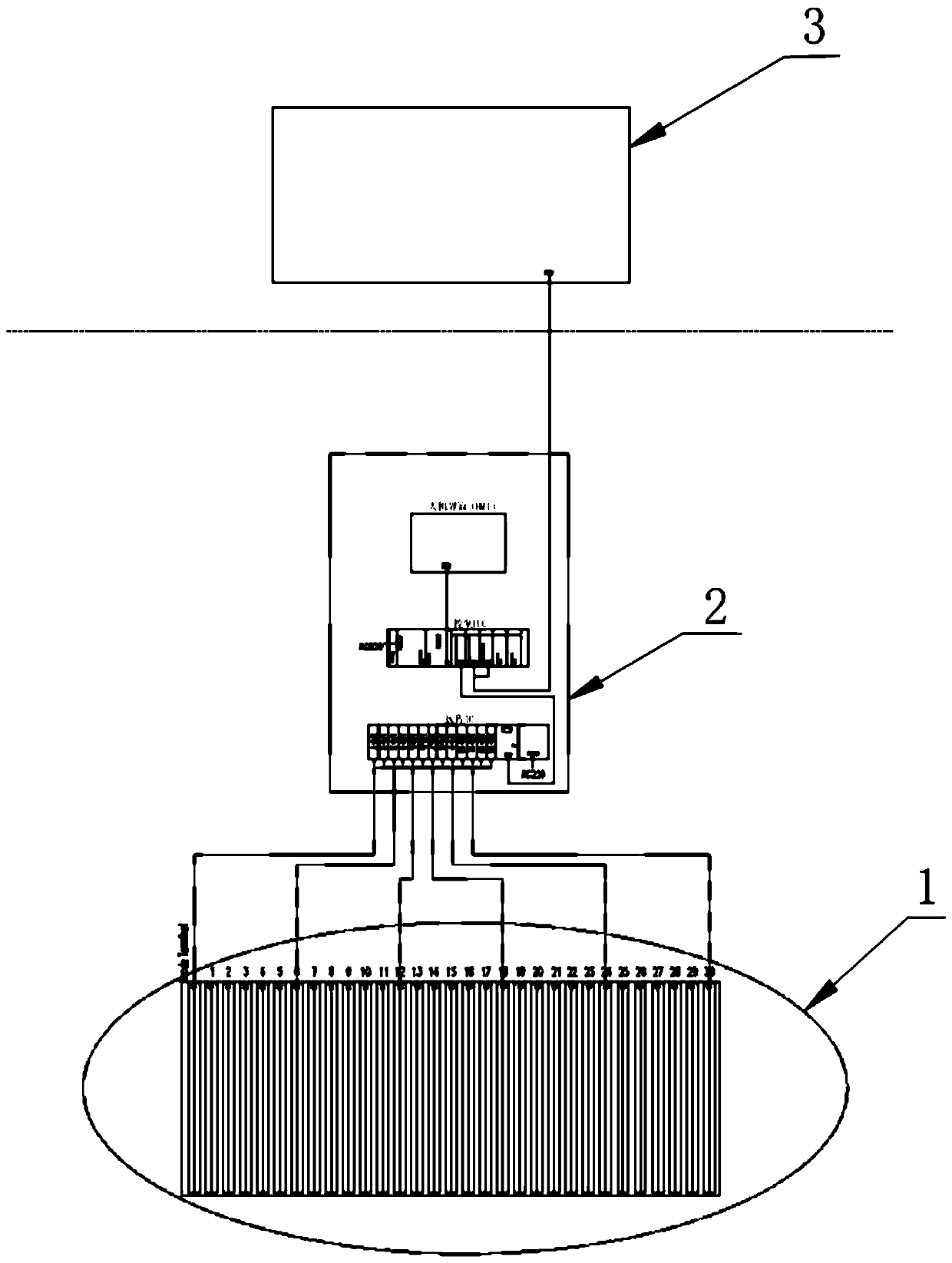
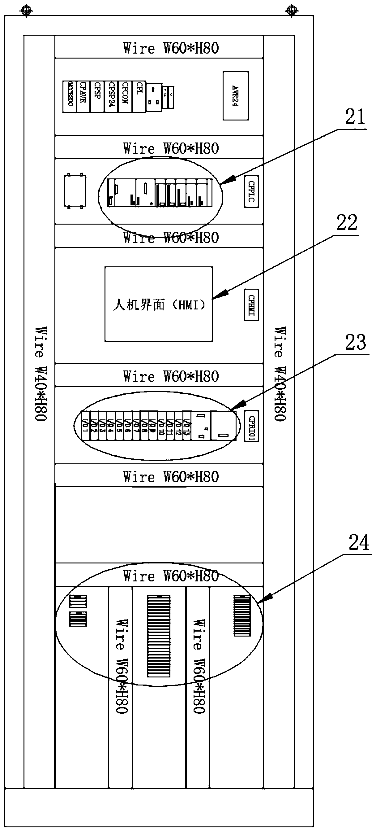
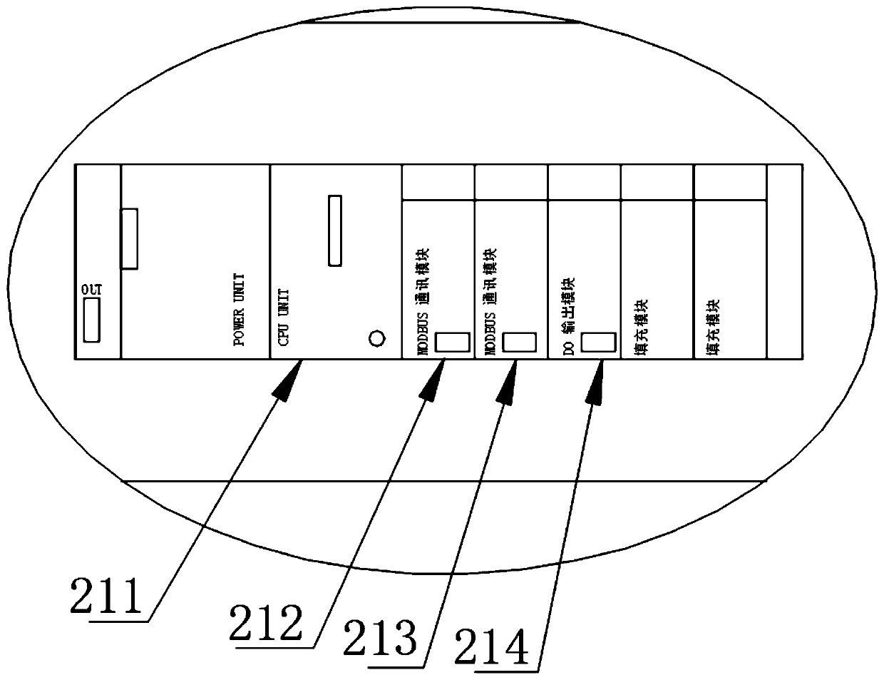
The invention discloses a bath voltage safety interlocking control device for an ionic membrane caustic soda electrolytic bath, and relates to the technical field of electrolytic bath voltage safety control. The bath voltage safety interlocking control device comprises the electrolytic bath, a control cabinet and a DSC control room, wherein the control cabinet and the DSC control room are electrically connected with the electrolytic bath in sequence; a control cabinet wiring area, a remote IO, a human-computer interface and a control PLC are arranged on the control cabinet; a control PLCCPU module, a first control PLC MODBUS communication module, a second control PLC MODBUS communication module and a control PLC DO output module are arranged on the control PLC; the electrolytic bath is composed of a plurality of unit cells; and a TB-1 electrolytic bath group voltage measurement wiring terminal is used for connecting a wire to a remote IO voltage acquisition module to realize acquisition of voltage signals of each group of voltage cells. According to the cell voltage safety interlocking control device, the driving process and normal operation safety of the electrolytic bath are protected through the three groups of alarm interlocking control schemes, and the monitoring of the safe operation condition of the electrolytic bath by a central control personnel is facilitated.

Description

technical field [0001] The invention belongs to the technical field of cell voltage safety control of an electrolyzer, in particular to a cell voltage safety interlock control device for an ion-exchange membrane caustic soda electrolyzer. Background technique [0002] The voltage detection of the existing ionic membrane caustic soda electrolyzer adopts artificial periodic detection. The disadvantages of this scheme include: 1. The electrolytic cell is a high-current device, and manual detection is a high-risk operation, and safety cannot be guaranteed; 2. The voltage data error of the manual detection cell is relatively large; 3. The manual detection cell voltage data record is incoherent. Voltage and voltage changes cannot be sensed in time; 4. Manual detection cannot be used as safety interlock control, which is passive detection; 5. Manual detection of electrolyzer voltage requires a large amount of on-site human resources and high labor costs; therefore, to solve the abo...

Claims


Application Information

Patent Timeline
Patent Type & Authority Applications(China)
IPC IPC(8): G05B19/05
CPCG05B19/058G05B2219/14006
Inventor 蒋闯宋剑萍张晓俊
Owner 上海芮晨机电设备有限公司
Features
  • R&D
  • Intellectual Property
  • Life Sciences
  • Materials
  • Tech Scout
  • Unparalleled Data Quality
  • Higher Quality Content
  • 60% Fewer Hallucinations
Learn More