[0016] All the features disclosed in this specification, or all disclosed methods or steps in the process, except for mutually exclusive features and/or steps, can be combined in any manner.
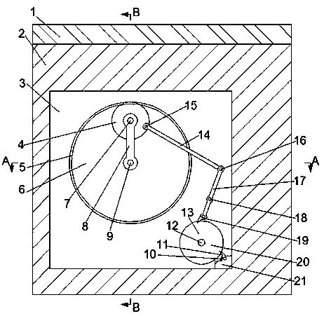
[0017] Combine below Figure 1-4 The present invention will be described in detail. For the convenience of description, the orientations mentioned below are now specified as follows: figure 1 The vertical, horizontal, front and rear directions of the projection relationship are the same.
[0018] A traffic control system device for a short-term parking section of the device of the present invention includes a short-term parking section 1. The bottom wall of the short-term parking section 1 is fixedly provided with a box body 2, and the short-term parking section 1 is provided There is a first chute 46 communicating up and down, a connecting mechanism located on the lower side of the first chute 46 is provided in the box body 2, a bevel gear cavity 22 is provided in the box body 2, and the bevel gear cavity 22 is A first bevel gear 23 is provided, and the first bevel gear 23 is fixedly connected to the first bevel gear shaft 9, and the first bevel gear shaft 9 is rotatably connected to the box body 2. A fixed ring groove 6 on the front side of the bevel gear cavity 9 and opening forward. The inner wall of the fixed ring groove 6 is fixedly provided with an inner gear ring 5, and the front end wall of the fixed ring groove 6 is provided with a stop groove 3. The front end of a bevel gear shaft 9 is provided with a long-term stop mechanism located in the stop slot 3, the box 2 is provided with a first gear cavity 31 located on the front side of the stop slot 3, and the first gear cavity 31 A first gear 30 is provided therein, and the first gear 30 is in meshing connection with a second gear 29 located above it, and the second gear 29 is fixedly connected with a camshaft 28, and the camshaft 28 is rotatably connected with the housing 2 An air intake mechanism is provided at the front end of the camshaft 28, and a warning block mechanism is provided inside the right side of the box body 2 and the short-term parking section 1.
[0019] Advantageously, the connecting mechanism includes a first sliding block 32 located in the first sliding groove 46 and slidably connected to the first sliding groove 46. The bottom wall of the first sliding block 32 is symmetrically fixed with a second sliding block 45. The bottom wall of the slider 32 and the first sliding groove 46 are connected by a first spring 33. The box 2 is provided with a motor 34 located between the front and rear first sliders 32. The bottom wall of the motor 34 is powered A motor shaft 35 is connected. The lower end of the motor shaft 35 is matedly connected with a spline shaft 36, and the spline shaft 36 is matedly connected with an upper coupling 38, and the upper coupling 38 is located in the third sliding groove 39 and In its sliding connection, the lower end of the upper coupling 38 is fixedly connected with a thrust ring 44. The top wall of the thrust ring 44 contacts the bottom walls of the two front and rear second sliding blocks 45. The outer end of the thrust ring 44 is located in the second sliding block. The bottom wall of the thrust ring 44 and the second sliding groove 43 are connected by a second spring 37. The third sliding groove 39 is provided with a lower coupling located on the lower side of the upper coupling 38. Shaft 40, the lower coupling 40 is matedly connected with the second bevel gear shaft 41, the second bevel gear shaft 41 is rotatably connected with the housing 2, and the bottom end of the second bevel gear shaft 41 is located in the bevel gear cavity The second bevel gear 42 in 22 is fixedly connected, and the second bevel gear 42 is in meshing connection with the first bevel gear 23 located on the lower side thereof.
[0020] Advantageously, the long-term stop mechanism includes a planet carrier 8 fixedly connected to the front end of the first bevel gear shaft 9, the other end of the planet carrier 8 is rotatably connected to the planet wheel shaft 7, and the rear end of the planet wheel shaft 7 is connected to the planet wheel. 4 Rotational connection, the planetary wheel 4 is meshed and connected with the inner gear ring 5, the front end wall of the planetary wheel 4 is fixedly provided with a first rotating pin 15, and the front end of the first rotating pin 15 is rotatably connected with the first connecting rod 14. The other end of the first connecting rod 14 is rotatably connected with the second rotating pin 16, the front end of the second rotating pin 16 is rotatably connected with the second connecting rod 17, and the middle part of the second connecting rod 17 is rotatably connected with the rotating shaft 18. The rotating shaft 18 is fixedly connected to the rear end wall of the stop groove 3, and the front end wall of the bottom end of the second link 17 is provided with a pushing pawl 19, which is connected to the lower side of the second link 17 and located in the stop groove 3. The ratchet wheel 20 is slidably connected. A tension spring block 21 is fixedly provided on the bottom wall of the right side of the rest slot 3, and a thrust pawl 11 is provided in the tension spring block 21. The ratchet wheel 20 is slidably connected, the thrust pawl 11 is connected with the top wall of the tension spring block 21 through the tension spring 10, the ratchet wheel 20 is fixedly connected with the ratchet shaft 12, and the ratchet shaft 12 is rotatably connected with the box 2 , The front end of the ratchet shaft 12 is fixedly connected with the first gear 30.
[0021] Advantageously, the air intake mechanism includes a cam 27 fixedly connected to the front end of the cam shaft 28, the cam 27 is located in the cam cavity 74, the cam 27 is slidably connected to the roller 73, and the roller 73 is connected to the roller shaft 26. Rotating connection, the roller shaft 26 is fixedly connected to the concave block 25, the right end wall of the concave block 25 is fixedly connected to the third sliding block 72, the right side of the third sliding block 72 is provided with a fixed block 68, the A fourth sliding groove 69 is provided in the fixed block 68, and a fourth sliding block 70 is slidably connected to the fourth sliding groove 69, and the fourth sliding block 70 is fixedly connected to the right end wall of the third sliding block 72, The left end wall of the fourth sliding block 70 and the fourth sliding groove 69 are connected by a third spring 71, the left top wall of the fourth sliding groove 49 is fixedly provided with a first vent pipe 66, the first vent pipe The top end of 66 is fixedly connected to the second vent pipe 64, the left end of the second vent pipe 64 is fixedly connected to the third vent pipe 47, and the top end of the third vent pipe 47 extends out of the surface of the short-term parking section. A fourth air pipe 65 is fixedly provided on the top wall on the right side of the sliding groove 49, and a check valve 67 is provided in the fourth air pipe 65.
[0022] Advantageously, the warning block mechanism includes a folding airbag 62 fixedly connected to the top end of the fourth vent tube 65, the folding airbag 62 is located in the airbag cavity 60, and a warning block 57 is provided at the top of the folding airbag 62, the warning block 57 is provided with a yellow ring 58, the warning block 57 is provided with a red ring 59 located on the lower side of the yellow ring 58, the top end of the warning block is fixedly connected with the stop block 53, and the top wall of the short-term parking section 1 is provided with The spring groove 55 with upward opening, the bottom wall of the stop block 53 and the spring groove 55 are connected by a fourth spring 54, the bottom of the folded airbag 62 is fixedly connected to the first air outlet pipe 63, and the left end of the first air outlet pipe 63 It is fixedly connected to the second air outlet pipe 61, and an air outlet one-way valve 56 is arranged in the second air outlet pipe 61. The top wall of the short-term parking section 1 is provided with a fifth sliding groove 52 with an upward opening. The groove 52 is provided with a fifth slider 49 slidably connected to it, the fifth slider 49 is provided with a vent 51 communicating up and down, and the bottom wall of the fifth slider 49 is fixedly provided with a tightly closing cover 50, so The bottom wall of the fifth sliding block 49 and the fifth sliding groove 52 are connected by a fifth spring 48.
[0023] In the initial state, the first spring 33, the second spring 37, the third spring 71, the fourth spring 54, the fifth spring 48, and the tension spring 10 are all in a normal tension state ;
[0024] The sequence of mechanical actions of the entire device:
[0025] 1. The vehicle is parked on the short-term parking section 1, so that the first slider 32 and the fifth slider 49 move downwards, so that the second air outlet pipe 61 cannot discharge air and the upper coupling 38 is connected with the lower coupling 40, Turn on the motor 34, so that the motor shaft 35 rotates, the spline shaft 36 rotates, the second bevel gear shaft 41 rotates, and the second bevel gear 42 rotates, so that the first bevel gear 23 rotates, thereby causing the first bevel gear 23 to rotate. A bevel gear shaft 9 rotates, so that the planet carrier 8 rotates, so that the planet gear 4 rotates, so that the second connecting rod 17 swings, because the long-term stop mechanism will stay at the left and right extreme positions for a period of time, thereby realizing the second connection The lever 17 swings for a long time and swings once at a fixed time, so that the ratchet wheel 20 rotates, thereby realizing timing;
[0026] 2. The ratchet wheel 20 rotates, so that the ratchet shaft 12 rotates, so that the first gear 30 rotates, so that the second gear 29 rotates, so that the camshaft 28 rotates, so that the cam 27 rotates, so that the roller 73, the concave block 25. The third slider 72 and the fourth slider 70 move repeatedly to inflate the foldable airbag 62, thereby causing the warning block 57 to move upwards. As time increases, the yellow ring 58 and the red ring 59 will appear on the ground in sequence Play a warning and display role;
[0027] 3. When the device needs to be reset, the vehicle drives away from the short-term parking section 1, so that the first sliding block 32 and the fifth sliding block 49 move upward, so that the second air outlet pipe 61 vents and the upper coupling 38 and the lower coupling 40 is disconnected, so that the spline shaft 36 stops rotating, so that the second bevel gear shaft 41 stops rotating, so that the second bevel gear 42 stops rotating, so that the first bevel gear 23 stops rotating, thereby making the first bevel gear The shaft 9 stops rotating, so that the planet carrier 8 stops rotating, so that the planetary wheel 4 stops rotating, so that the second link 17 stops swinging, so that the ratchet 20 stops rotating, so that the ratchet shaft 12 stops rotating, so that the first The gear 30 stops rotating, so that the second gear 29 stops rotating, so that the camshaft 28 stops rotating, so that the cam 27 stops rotating, so that the roller 73, the concave block 25, the third slider 72 and the fourth slider 70 The repeated movement is stopped, the air in the folded airbag 62 is discharged from the second air outlet pipe 61 under the downward movement of the warning block 57 due to gravity, and the device is reset.
[0028] The above are only specific embodiments of the invention, but the scope of protection of the invention is not limited to this. Any changes or substitutions that are not thought of through creative work should be covered by the scope of protection of the invention. Therefore, the protection scope of the invention should be subject to the protection scope defined by the claims.