Metallic wall section cooling method

A cooling method and metal wall technology, which can be used in cooling devices, pipeline heating/cooling, nuclear power generation, etc., can solve problems such as reduced operating efficiency, and achieve the effects of prolonging creep life and preventing damage

Active Publication Date: 2020-05-01
MITSUBISHI POWER LTD
View PDF8 Cites 0 Cited by
  • Summary
  • Abstract
  • Description
  • Claims
  • Application Information

AI Technical Summary

Problems solved by technology

When the result of the non-destructive inspection shows that the risk of creep damage during the period until the next periodic inspection cannot be ignored, the risk of creep damage may be reduced by lowering the operating temperature of the entire plant to lower the metal temperature of the metal piping. countermeasures, but if the overall operating temperature of the plant is lowered, there is a disadvantage that the operating efficiency of the plant will decrease

Method used


Image

  • Metallic wall section cooling method
  • Metallic wall section cooling method
  • Metallic wall section cooling method

Examples


no. 1 approach

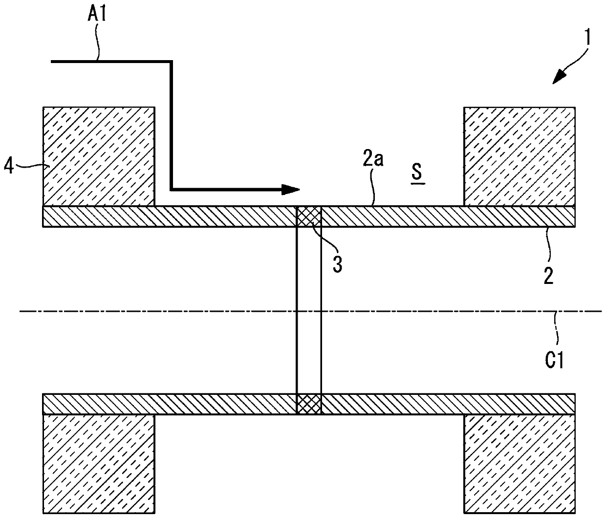
[0043] exist figure 1 The pipe cooling structure 1 which locally cools the pipe (metal wall part) used as a cooling object is shown in FIG. The heat insulating material 4 is arranged on the outer periphery of the pipe 2 . In the pipe 2 , a welded portion 3 is formed in the circumferential direction (pipe circumferential direction), and a space S is formed by removing a part of the heat insulating material 4 in a region including the welded portion 3 . Through the space S, the outer surface 2a of the pipe 2 is exposed to the outside (atmosphere). In addition, when the welded part is formed in the pipe axial direction, the thermal insulation material 4 is partially removed so that the region along the welded part formed in the pipe axial direction is exposed.

[0044] The piping 2 is a circular pipe having a central axis C1, and low alloy steel (1.25Cr-Mo steel or 2.25Cr-Mo steel, etc.), high Cr steel (9Cr steel), austenitic steel (SUS316 ), Ni-based alloy steel (HR6W) and ot...

no. 2 approach

[0095] Next, a second embodiment will be described.

[0096] This embodiment is different from the first embodiment in that the temperature distribution in the pipe axis direction of the pipe 2 is considered, but the other points are the same. Therefore, differences from the first embodiment will be described below.

[0097] Ruo Ru figure 1 Removing only a part of the thermal insulation material 4 in the pipe axis direction of the pipe 2 as shown will generate a temperature distribution in the pipe axis direction. If temperature distribution occurs in the tube axis direction, thermal stress will further occur due to the temperature distribution.

[0098] Expressing this in a coordinate diagram becomes Figure 8 like that. As shown in the figure, according to the overlapping of the thermal stress due to the temperature distribution in the tube axis direction, the stress becomes higher as in the curve L6 compared to the curve L4 which does not consider the thermal stress. T...

no. 3 approach

[0102] Next, a third embodiment will be described.

[0103] In the second embodiment, the target post-cooling temperature is corrected based on the temperature distribution in the tube axis direction and the tube circumference direction, but it is necessary to grasp the temperature distribution in the tube axis direction and the tube circumference direction generated in the pipe 2 . On the other hand, this embodiment provides a simpler cooling method by limiting the temperature distribution in the tube axial direction and the tube peripheral direction to a predetermined range.

[0104] Such as Figure 9 As shown, in step S11, the temperature decrease amount is set. The amount of temperature reduction means that from Figure 8 The temperature difference from plot point P1 to the target post-cooling temperature is shown. Therefore, it is the amount of temperature drop exceeding the temperature range ΔT1' from the plot point P1, and the target after-cooling temperature determi...


PUM


Abstract

Provided is a metallic wall section cooling method for partially cooling the outer surface of a pipe for circulating steam. The temperature of a pressurized fluid is 500-700 DEG C and the temperatureof the outer surface of the pipe is at least 200 DEG C. The temperature difference in the plate thickness direction of the pipe is no greater than 300 DEG C. The temperature difference at a cooled portion in the pipe axial direction of the pipe is 500 DEG C if the dimension of the pipe in the pipe axial direction is within the range of +/-100 mm. The temperature difference in the pipe circumferential direction of the pipe is no greater than 50 DEG C.

Description

technical field [0001] The present invention relates to a metal wall cooling method for cooling pipes and pressure vessels used in thermal power plants, nuclear power plants, chemical plants, and the like. Background technique [0002] For example, in a thermal power plant, piping is arranged to transport steam heated by a boiler to a steam turbine. The piping is a metal piping, and since high-temperature and high-pressure water vapor flows inside, it is in an environment of a high-temperature state heated by the water vapor. When such a metal pipe is used for a long time under the above-mentioned environment, creep damage progresses to generate creep holes, and the creep holes connect to each other to generate cracks and eventually break. [0003] In order to prevent such breakage of piping, the degree of growth of creep holes is analyzed by periodic non-destructive testing to derive the degree of creep damage, and the remaining life (creep life) of metal piping is evaluat...

Claims


Application Information

Patent Timeline
Patent Type & Authority Applications(China)
IPC IPC(8): F16L57/00F16L53/70G21D1/00
CPCY02E30/00G21D1/02G21C15/12Y02E30/30
Inventor 渡边大刚加藤千香子坂田文稔松尾毅浦下靖崇大山博之
Owner MITSUBISHI POWER LTD
Why Eureka
Try Eureka