Medical instrument shell paint spraying device

A technology for medical devices and shells, applied in the field of painting devices for medical device shells, can solve the problems of affecting the surface finish of beautiful products, waste of paint, etc., and achieve the effects of accelerating the solidification speed, ensuring the surface quality, and avoiding uneven spraying.

Pending Publication Date: 2020-05-05
深圳市佳鑫一帆科技有限公司
View PDF0 Cites 3 Cited by
  • Summary
  • Abstract
  • Description
  • Claims
  • Application Information

AI Technical Summary

Problems solved by technology

[0004] If the existing paint spraying device wants to spray paint evenly on the product, it is necessary to control the rotation of the product and spray paint continuously during the rotation process. Although this method can make the paint evenly cover the outer surface of the product, it is also easy to cause the paint to be damaged. The problem of a lot of waste, especially for products with a large volume such as the outer shell, and during the continuous rotation of the product, the paint that touches the outer wall of the product will be thrown out fine lines or even solidified under the action of centrifugal force Tumors will seriously affect the appearance and product surface finish

Method used


Image

  • Medical instrument shell paint spraying device
  • Medical instrument shell paint spraying device
  • Medical instrument shell paint spraying device

Examples


Embodiment Construction

[0030] The following will clearly and completely describe the technical solutions in the embodiments of the present invention with reference to the accompanying drawings in the embodiments of the present invention. Obviously, the described embodiments are only some, not all, embodiments of the present invention.

[0031] In the description of the present invention, unless otherwise stated, the meaning of "plurality" is two or more; the terms "upper", "lower", "left", "right", "inner", "outer" , "front end", "rear end", "head", "tail", etc. indicate the orientation or positional relationship based on the orientation or positional relationship shown in the drawings, and are only for the convenience of describing the present invention and simplifying the description, rather than Nothing indicating or implying that a referenced device or element must have a particular orientation, be constructed, and operate in a particular orientation should therefore not be construed as limiting ...


PUM


Abstract

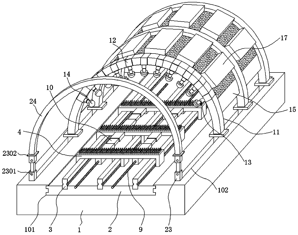
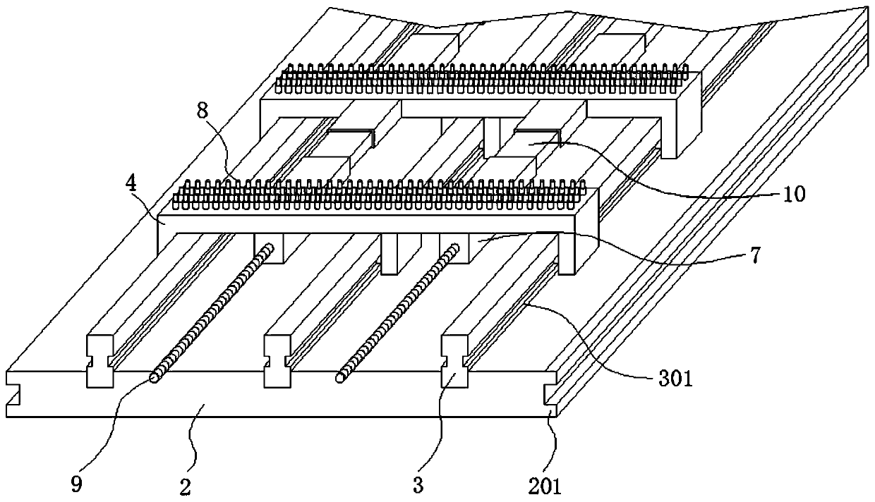
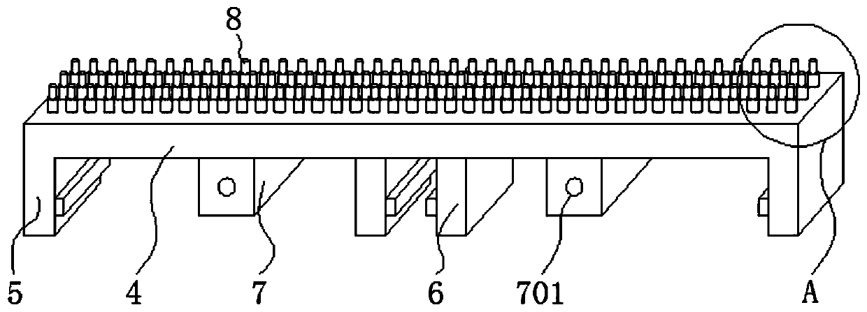
The invention discloses a medical instrument shell paint spraying device and relates to the technical field of medical instrument shell paint spraying devices. The medical instrument shell paint spraying device specifically comprises a horizontal table, a slide plate, supporting plates, paint spraying frames and a drying frame; the middle of the upper surface of the horizontal table is provided with a shifting groove; the slide plate is assembled in the shifting groove in a sliding manner; the supporting plates are assembled above slide rails in a sliding manner; telescopic plates are connected between the supporting plates; the two ends of each paint spraying frame are both inserted into clamping grooves; arc connection plates are connected between the paint spraying frames; and the two ends of the drying frame are correspondingly fixed to flat plates. The medical instrument shell paint spraying device is applicable to paint spraying machining of shells in various sizes, uniform paintspraying treatment can be performed on the shells, uniform smearing on paint adhering to the surfaces of the shells can be performed during paint spraying or after paint spraying, and therefore the problems that spraying is not uniform, bubbles are left in the spraying face, the consuming amount is large in one time of spraying, and waste is caused easily are solved, and the surface quality of aspraying face can be guaranteed.

Description

technical field [0001] The invention relates to the technical field of a paint spraying device for a medical device shell, in particular to a paint spraying device for a medical device shell. Background technique [0002] In order to protect the internal parts of the medical device, it is necessary to use the shell. The shell of the medical device is mostly made of plastic or metal, and it is produced by the mold forming process. In addition to fine processing such as grinding and deburring of the shell, in order to To improve the aesthetics of the entire medical device product, it is also necessary to paint and decorate the device casing. [0003] The modern painting method is to spray the paint evenly on the object with a nozzle, and then make the object rotate for a circle. During the rotation process, the paint is evenly sprayed. After the spraying, the paint is dried to a condensed state with a heat drying structure. [0004] If the existing paint spraying device wants...

Claims


Application Information

Patent Timeline
Patent Type & Authority Applications(China)
IPC IPC(8): B05B16/20B05B13/02B05B15/00B05B15/68B05B14/00B05D3/02B05D3/04
CPCB05B13/0292B05B14/00B05B15/00B05B15/68B05B16/20B05D3/0254B05D3/0406
Inventor 段平泉邓美姣
Owner 深圳市佳鑫一帆科技有限公司
Why Eureka
Try Eureka