In-situ cementing assembling method for satellite composite material truss

A composite material and truss technology, which is applied in the field of in-situ bonding and assembly of satellite composite trusses, can solve problems such as affecting hole position accuracy, increasing repair workload, and poor shape accuracy, reducing the use of machining equipment and avoiding machine tools. Machining benchmark error, reducing the effect of process flow

Active Publication Date: 2020-05-05
SHANGHAI COMPOSITES SCI & TECH CO LTD
View PDF21 Cites 11 Cited by
  • Summary
  • Abstract
  • Description
  • Claims
  • Application Information

AI Technical Summary

Problems solved by technology
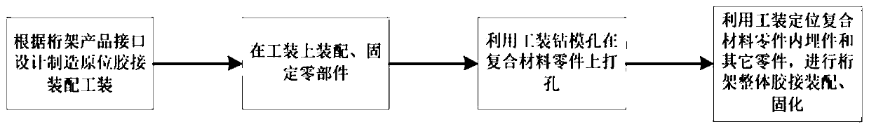
[0004] 1. After the composite material part is formed, its shape accuracy is relatively poor, and it is difficult to find an accurate benchmark for processing during the drilling process;
[0005] 2. Since the parts are processed separately, the cumulative error of the hole position will easily lead to the difficulty of complete fitting on the tooling, which will increase the workload of repair and affect the accuracy of the hole position. At the same time, excessive repair of composite materials will lead to an increase in the scrap rate of parts;
[0006] 3. During the entire truss development and production process, composite materials are processed by machine tools, and the processing cannot fully meet the subsequent assembly requirements, resulting in high cost and low efficiency
However, this method performs drilling, pre-fitting, and bonding of embedded parts in the state of composite material parts. After the composite material parts are formed, the shape accuracy is relatively poor. During the drilling process, it is difficult to find an accurate benchmark for processing; and because Holes are processed separately for parts, and the cumulative error of the hole position is likely to make it difficult to fully fit the tooling, increasing the workload of repairing and affecting the accuracy of the hole position. At the same time, excessive repairing of composite materials leads to an increase in the scrap rate of parts

Method used


Image

  • In-situ cementing assembling method for satellite composite material truss

Examples


Embodiment Construction

[0038] The present invention will be described in detail below in conjunction with specific embodiments. The following examples will help those skilled in the art to further understand the present invention, but do not limit the present invention in any form. It should be noted that those skilled in the art can make several changes and improvements without departing from the concept of the present invention. These all belong to the protection scope of the present invention.

[0039] In the description of this application, it should be understood that the terms "upper", "lower", "front", "rear", "left", "right", "vertical", "horizontal", "top", The orientation or positional relationship indicated by "bottom", "inner", "outer", etc. is based on the orientation or positional relationship shown in the drawings, and is only for the convenience of describing the application and simplifying the description, rather than indicating or implying the referred device Or elements must hav...


PUM


Abstract

The invention provides an in-situ cementing assembling method for a satellite composite material truss. The in-situ cementing assembling method for the satellite composite material truss comprises thefollowing steps that 1, an in-situ cementing assembling tool is designed and manufactured according to the truss structure and ports; 2, truss parts are assembled and fixed on the in-situ cementing assembling tool; 3, the truss parts are punched through a drill jig hole of the in-situ cementing assembling tool; and 4, the truss assembling parts and embedded parts in the truss parts are positionedthrough a positioning hole of the in-situ cementing assembling tool, and truss assembling positioning, cementing and solidifying are conducted. According to the in-situ cementing assembling method for the satellite composite material truss, the purpose that all installing hole of the truss are punched, positioned, cemented and solidified on the same standard can be achieved, repairing of the composite material parts can be effectively reduced, and the assembling precision is improved; and machining standard errors brought by composite material appearance deviation are effectively avoided, andthe machining problems brought due to the fact that the composite material parts cannot set the precise machining standards are avoided.

Description

technical field [0001] The invention relates to the field of assembly of composite material structural parts, in particular to a method for in-situ adhesive bonding assembly of satellite composite material trusses. Background technique [0002] Composite truss is a commonly used load-bearing structure for satellites and space vehicles. It is generally manufactured by bonding carbon fiber composite parts and metal embedded parts. Composite materials are used to provide load support, and metal embedded parts in composite materials are used to provide satellite load interfaces. . Therefore, the truss structure has high requirements on the hole position and flatness of the interface position, but relatively low requirements on the external dimensions of the composite rods and joints. [0003] At present, conventional truss assembly and processing are mostly carried out in the traditional way, that is, punching holes in the state of composite parts, pre-fitting, gluing embedded ...

Claims


Application Information

Patent Timeline
Patent Type & Authority Applications(China)
IPC IPC(8): B29C65/48B29C65/78B29C69/00B26F1/00B26F1/16B26D7/01
CPCB26D7/01B26F1/0084B26F1/16B29C65/48B29C65/7802B29C69/00
Inventor 李晓晓李宗周胡宗文周丽珏吴春燕邵劲力董斌叶周军
Owner SHANGHAI COMPOSITES SCI & TECH CO LTD
Why Eureka
Try Eureka