
Convenient feeding device based on sheet-metal working
A convenient and sheet metal technology, applied in the direction of metal processing equipment, feeding devices, positioning devices, etc., can solve the problems of misalignment of sheet metal, consume labor and physical strength of staff, reduce sheet metal processing efficiency, etc., and achieve lengthening and use Safe and convenient, scientific and reasonable structure
- Summary
- Abstract
- Description
- Claims
- Application Information
AI Technical Summary
Problems solved by technology
Method used
Image

Examples
Embodiment
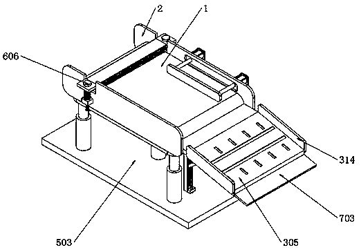
[0044] Example: such as Figure 1-8 As shown, the present invention provides a technical solution, a convenient feeding device based on sheet metal processing, including a conveyor belt 1, and baffles 2 are installed on both sides of the conveyor belt 1 through screws;
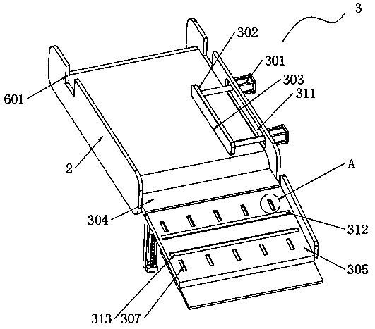
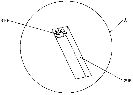
[0045]An alignment assembly 3 is installed on the top of the conveyor belt 1, and the alignment assembly 3 includes a cylinder 301, a push plate 302, a rubber plate 303, a connecting plate 304, a slide plate 305, a vertical groove 306, a first roller 307, a mounting groove 308, an arc plate 309, and a ratchet 310, the corresponding groove 311, the transverse groove 312 and the second roller 313;
[0046] A baffle plate 2 is equipped with a cylinder 301 at both ends of the middle part on one side, and a push plate 302 is installed at one end of the cylinder 301, and a rubber plate 303 is bonded to one end of the push plate 302, and the length and width of the rubber plate 303 are respectively the same as the le...
PUM
 Abstract
Description
Claims
Application Information