A tinning machine for battery wire joints

A technology of wire joints and tin machines, applied in welding equipment, tin feeding devices, welding/welding/cutting items, etc., can solve problems such as low efficiency, damaged wire sheath, and difficulty in controlling the soaking time and depth of wires, etc. Achieve high efficiency and avoid damage

Active Publication Date: 2021-06-11
龚杰
View PDF5 Cites 0 Cited by
  • Summary
  • Abstract
  • Description
  • Claims
  • Application Information

AI Technical Summary

Problems solved by technology

[0004] In order to overcome that people can only tin one wire at a time, resulting in low efficiency, and the temperature of the tin after melting is about 100 degrees Celsius to 200 degrees Celsius, and it is difficult for people to control the soaking time and depth of the wire, which is easy to cause heat. The shortcoming of damaging the wire sheath due to the conduction from the wire core to the wire sheath, technical problem: to provide a battery wire connector tinning machine that can tin multiple wires at one time, has high efficiency, and can avoid damage to the wire sheath

Method used


Image

  • A tinning machine for battery wire joints
  • A tinning machine for battery wire joints
  • A tinning machine for battery wire joints

Examples


Embodiment 1

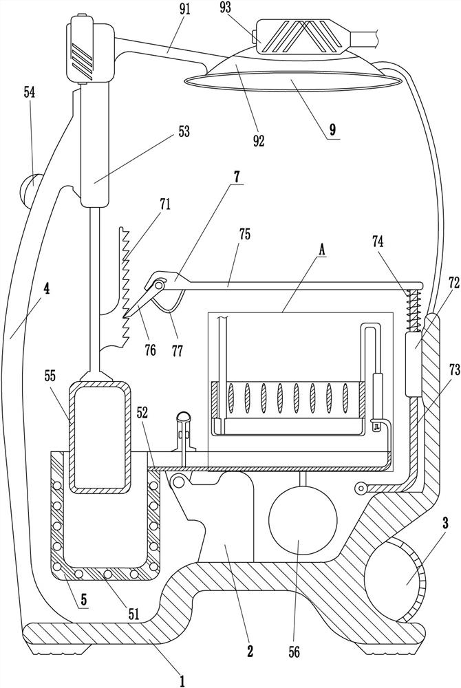
[0026] A tinning machine for battery wire joints, such as Figure 1-2 As shown, it includes an organic base 1, a fixed plate 2, a vertical rod 4, a tinning mechanism 5, and a tin immersion mechanism 6. The top of the machine base 1 is welded with a fixed plate 2 and a vertical rod 4, and the vertical rod 4 is located on the left side of the fixed plate 2. The fixed plate 2 is provided with a tinning mechanism 5, which is used to dissolve the tin bar into liquid tin, and the tinning mechanism 5 is provided with a tin-immersing mechanism 6, which is used to soak the wire in liquid tin .

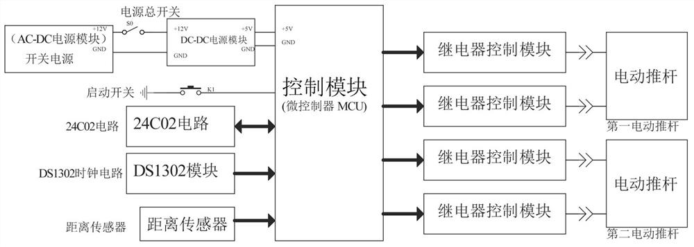
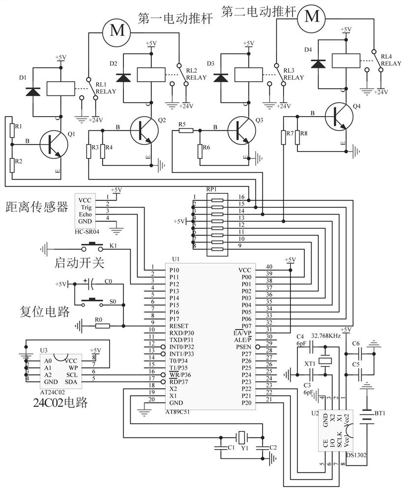
[0027] It also includes a control module, and both the tinning mechanism 5 and the tin immersion mechanism 6 are electrically connected to the control module.

[0028] The tin loading mechanism 5 includes a tin melting furnace 51, a tin tank 52, a first electric push rod 53, a start switch 54, a filling block 55, a counterweight ball 56 and a distance sensor 57. Slot 52, the bottom of the tin...

Embodiment 2

[0034] On the basis of Example 1, such as figure 1 and image 3 As shown, it also includes a surplus material dumping mechanism 7, and the surplus material dumping mechanism 7 includes a toothed plate 71, a guide sleeve 72, a guide rod 73, a spring 74, a cross bar 75, a ratchet 76 and a shrapnel 77, and the first electric push rod 53 The right side of the expansion rod is connected with a tooth plate 71 by bolts, and a guide sleeve 72 is installed on the upper left side of the base 1, and a guide rod 73 is slidably arranged in the guide sleeve 72, and a cross bar 75 is welded on the top of the guide rod 73, and a cross bar 75 A spring 74 is connected between the guide sleeve 72, the spring 74 is wound on the guide rod 73, the left end of the cross bar 75 is hingedly connected with a pawl 76, the pawl 76 cooperates with the tooth plate 71, and the pawl 76 and the cross bar 75 are connected There are shrapnel 77.

[0035] Also includes a filter mechanism 8, the filter mechanis...


PUM


Abstract

The invention relates to a tinning machine, in particular to a tinning machine for battery wire joints. The technical problem is how to provide a battery wire connector tinning machine capable of tinning multiple wires at one time with high efficiency and avoiding wire sheath damage. The invention discloses a tinning machine for battery wire joints, which includes an organic base, a fixing plate, a vertical rod, etc.; The present invention can tin the wires through the cooperation of the tinning mechanism and the tin immersion mechanism, so that multiple wires can be tinned at one time, with high efficiency, and the soaking time and depth of the wires can be precisely controlled mechanically, so that It can avoid damage to the wire sheath, and the tin tank can be pushed upwards to swing through the residual material dumping mechanism, so that all the liquid tin in the tin tank can flow back into the tin melting furnace to avoid liquid tin remaining in the tin tank.

Description

technical field [0001] The invention relates to a tinning machine, in particular to a tinning machine for battery wire joints. Background technique [0002] Wire refers to the material used as wire and cable, generally made of copper or aluminum, and also made of silver wire, which is used to conduct current or heat conduction. When using wire, in order to improve conductivity, it is necessary to tin the wire. Now Generally, people manually soak the wire in the liquid tin in the tin melting furnace to tin the wire. People can only tin one wire at a time, resulting in low efficiency, and the temperature after the tin is melted is about 100 degrees Celsius. When the temperature reaches 200 degrees Celsius, it is difficult for people to control the soaking time and depth of the wire, which will easily lead to heat conduction through the wire core to the wire sheath, resulting in damage to the wire sheath. [0003] Therefore, it is necessary to develop a device capable of tinni...

Claims


Application Information

Patent Timeline
Patent Type & Authority Patents(China)
IPC IPC(8): B23K3/06B23K3/08B23K101/36
CPCB23K3/0607B23K3/0669B23K3/08B23K2101/36
Inventor 曾招炜
Owner 龚杰
Why Eureka
Try Eureka