Processing device

A processing equipment and station technology, applied in metal processing equipment, grinding/polishing equipment, manufacturing tools, etc., can solve the problems of messy detachable control wires, inconvenient movement and transportation, fixed polishing angle, etc., to achieve easy induction and travel line, improve production efficiency, and facilitate transportation and movement

Inactive Publication Date: 2020-05-08
嘉兴君宏汽车配件有限公司
View PDF0 Cites 0 Cited by
  • Summary
  • Abstract
  • Description
  • Claims
  • Application Information

AI Technical Summary

Problems solved by technology

[0002] At present, with the continuous development of medical device technology, more and more equipment for processing medical devices are used. In the process of processing medical devices, it is often necessary to polish them. The existing polishing machine has a high working efficiency. Low, the polishing angle is fixed, most of the polishing machines are fixed installations, it is inconvenient to move and transport, the detachable control wires between the stations are messy, the safety factor is low, and a large amount of debris will be generated during polishing, which is harmful to the human body, so a A processing equipment to improve the above problems

Method used


Image

  • Processing device
  • Processing device
  • Processing device

Examples


Embodiment Construction

[0021] The following will clearly and completely describe the technical solutions in the embodiments of the present invention with reference to the accompanying drawings in the embodiments of the present invention. Obviously, the described embodiments are only a part of the embodiments of the present invention, not all the embodiments, based on The embodiments of the present invention, and all other embodiments obtained by those of ordinary skill in the art without creative work, fall within the protection scope of the present invention.

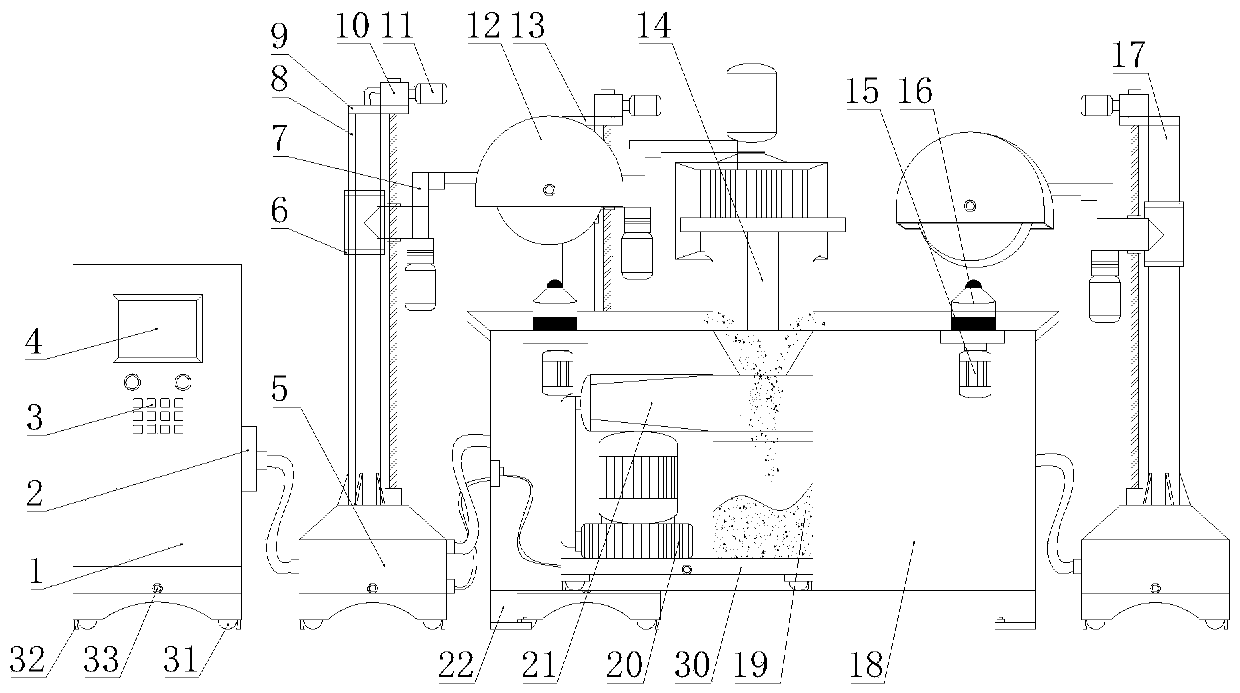
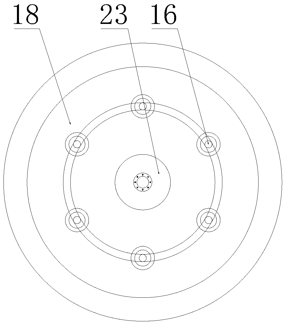
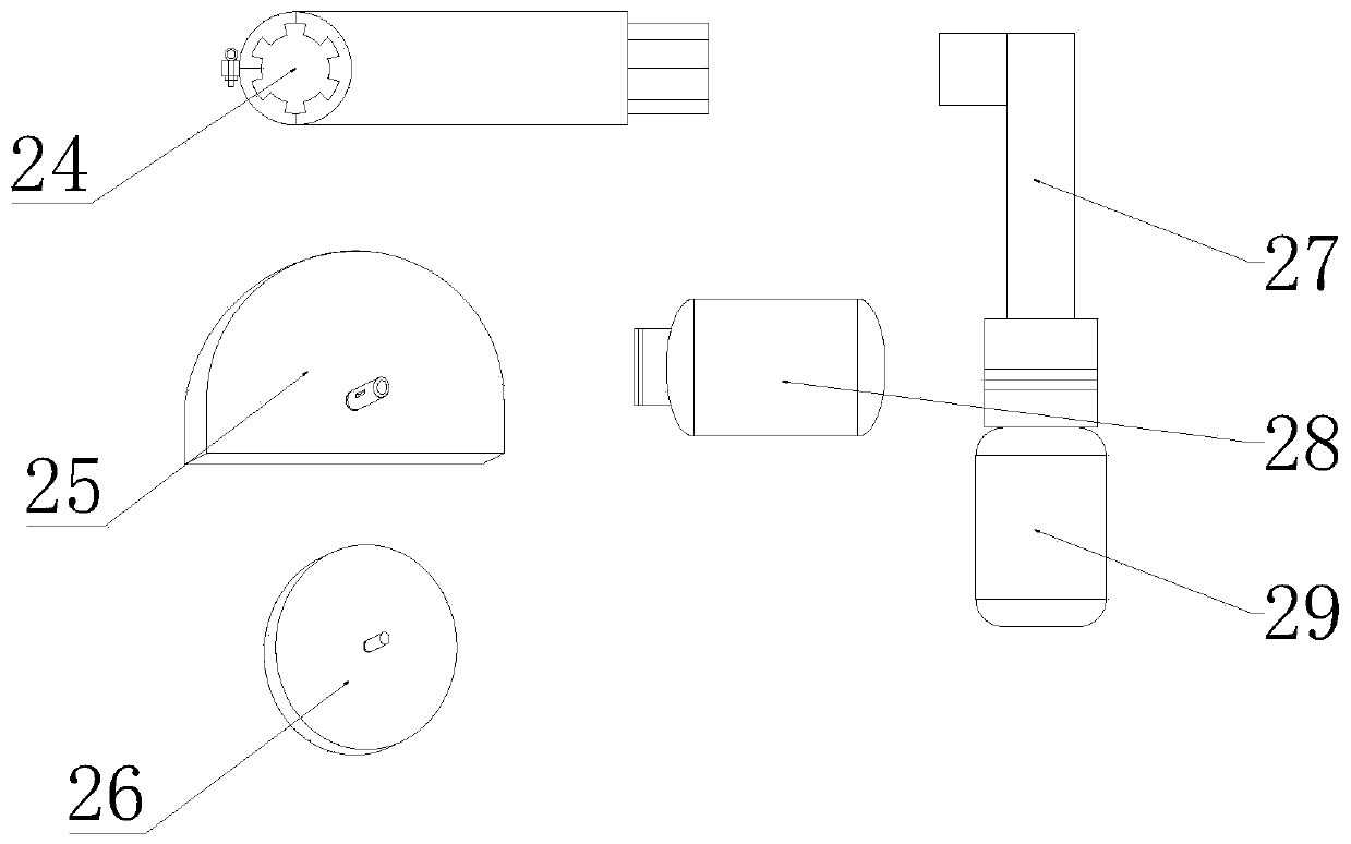
[0022] See Figure 1-3 , The present invention provides a technical solution:

[0023] A processing equipment includes a control cabinet 1, an operating platform 18, and a horizontal polishing machine 9. The base surface of the control cabinet 1 is provided with a display screen 4 and a control panel 3, and a connector 2 is fixedly installed on the right side of the control cabinet 1. There is a station level polishing machine 9 on the right sid...


PUM


Abstract

The invention relates to the technical field of mechanical processing devices, in particular to a processing device. The processing device comprises a control cabinet, an operating platform and a one-station horizontal polishing machine; a base surface of the control cabinet is provided with a display screen and a control panel; a connector is fixedly mounted on the right side of the control cabinet; the one-station horizontal polishing machine is arranged on the ground on the right side of the control cabinet; the one-station polishing machine comprises a base, a positioning loop bar, a transmission mechanism, a hollow support rod, a screw drive and a screw motor; the operating platform is arranged on the ground on right side of the one-station horizontal polishing machine; a plurality ofpositioning seats distributed circumferentially are arranged at the upper end of the operating platform; a chip inlet is formed in the center of the upper end of the operating platform; a chip collecting barrel is arranged at the lower end of the chip inlet; an air suction port is fixedly mounted in the left side of the upper part of the chip collecting barrel; a mobile table is arranged at the lower end of the chip collecting barrel; and a suction fan is fixedly installed on the left side of the upper end of the mobile table. The whole processing device is good in effect, is higher in stability and practicality, and has a certain promotion value.

Description

Technical field [0001] The invention relates to the technical field of mechanical processing equipment, in particular to a processing equipment. Background technique [0002] At present, with the continuous development of medical device technology, more and more equipment is used for processing medical devices. In the process of processing medical devices, it is often necessary to polish them. The existing polishing machines work efficiently. Low, the polishing angle is fixed, the polishing machine is mostly fixed installation, it is inconvenient to move and transport, the detachable control wires between the stations are more messy, the safety factor is low, and a large amount of debris will be generated during polishing, which is harmful to the human body. This kind of processing equipment improves the above problems. Summary of the invention [0003] The purpose of the present invention is to provide a processing equipment to solve the above-mentioned background art problems. ...

Claims


Application Information

Patent Timeline
Patent Type & Authority Applications(China)
IPC IPC(8): B24B29/02B24B27/00B24B55/06B24B55/00B24B51/00B24B47/12
CPCB24B27/0007B24B27/0023B24B27/0076B24B29/02B24B47/12B24B51/00B24B55/00B24B55/06
Inventor 陈立峰
Owner 嘉兴君宏汽车配件有限公司
Why Eureka
Try Eureka