Lifting type charging device for new energy automobile

A new energy vehicle and charging device technology, applied in electric vehicle charging technology, charging stations, electric vehicles, etc., can solve problems such as being vulnerable to impacts, and achieve effective protection

Inactive Publication Date: 2020-05-08
张和平
View PDF0 Cites 9 Cited by
  • Summary
  • Abstract
  • Description
  • Claims
  • Application Information

AI Technical Summary

Problems solved by technology

[0003] Existing charging piles are located above the ground for a long time and are vulnerable to impact

Method used


Image

  • Lifting type charging device for new energy automobile
  • Lifting type charging device for new energy automobile
  • Lifting type charging device for new energy automobile

Examples


Embodiment 1

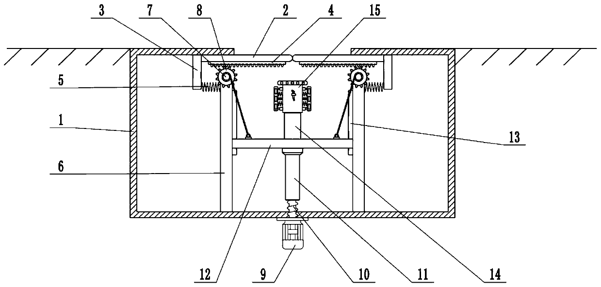
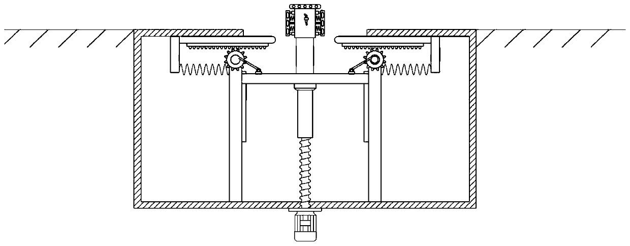
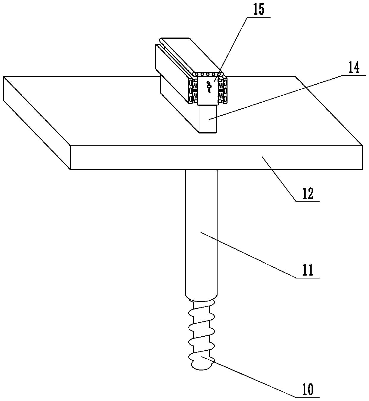
[0025] see Figure 1-4 , in an embodiment of the present invention, a special elevating charging device for new energy vehicles, comprising a box body 1, a lifting plate 12, a fixed platform 14 and a charging pile 15, the box body 1 is buried in the ground, and the upper surface of the box body 1 is in contact with the ground The upper surface of the box body 1 is provided with a through hole, and the top of the box body 1 is equipped with a movable plate 2. There are two movable plates 2, which are arranged symmetrically on the left and right. The upper surface of the movable plate 2 is slidingly connected with the top of the box body 1. , the movable plate 2 can slide left and right along the top of the box body 1, the end of the movable plate 2 is fixedly connected with the fixed block 3, the inside of the box body 1 is equipped with a support plate 6, and the support plate 6 is fixedly connected with the bottom of the box body 1 , the side wall of the fixed block 3 is fixe...

Embodiment 2

[0027] On the basis of Embodiment 1, guide cylinders 20 are installed on the left and right sides of the charging pile 15, and the inside of the guide cylinder 20 is slidably connected with a guide rod 21. The end of the guide rod 21 is connected with the anti-collision plate 18, and the charging pile The side wall of 15 is distributed with damping spring 22, and the end of damping spring 22 is fixedly connected with anti-collision plate 18, utilizes damping spring 22 to further absorb the energy that impact produces, and more effectively protects charging pile 15.

[0028] Combined with Embodiment 1 and Embodiment 2, the working principle of the present invention is: under normal conditions, the charging pile 15 is inside the box body 1, and the movable plate 2 is in a closed state. When it is necessary to charge the new energy vehicle, it is necessary to use The charging pile 15 rises to the ground, starts the motor 9, drives the screw rod 10 to rotate, thereby drives the lif...


PUM


Abstract

The invention relates to the field of new energy vehicles. More particularly, the present invention relates to a lifting type charging device for a new energy automobile. The lifting type charging device comprises a box body, a lifting plate, a fixed table and a charging pile, wherein a through hole is formed in the upper surface of the box body; a movable plate is mounted at the top of the box body; the end part of the movable plate is fixedly connected with a fixed block; a supporting plate is mounted in the box body; the side wall of the fixed block is fixedly connected with a force storagespring; a rack is mounted on the lower surface of the movable plate; the top of the supporting plate is rotationally connected with a rotating shaft; a gear is arranged on the rotating shaft; the bottom of the box body is fixedly connected with a motor; the shaft extension end of the motor is fixedly connected with a screw rod; the upper end of the lead screw is sleeved with a sleeve; the top ofthe sleeve is fixedly connected with the lifting plate, the upper surface of the lifting plate is fixedly connected with the fixed table; the top of the fixed table is fixedly connected with the charging pile; a motor is used for driving the charging pile to be lifted upwards, meanwhile, the movable plate is opened such that the charging pile is lifted to the ground, and people can charge the newenergy automobile conveniently.

Description

technical field [0001] The invention relates to the field of new energy vehicles, more specifically, a special lifting charging device for new energy vehicles. Background technique [0002] The function of the charging pile is similar to that of the fuel dispenser in the gas station. It can be fixed on the ground or on the wall, and installed in public buildings (public buildings, shopping malls, public parking lots, etc.) and residential area parking lots or charging stations. Charge all models of electric vehicles. The input end of the charging pile is directly connected to the AC grid, and the output end is equipped with a charging plug for charging the electric vehicle. [0003] Existing charging piles are located above the ground for a long time and are vulnerable to impact. Contents of the invention [0004] The purpose of the present invention is to provide a special lift-type charging device for new energy vehicles to solve the problems raised in the above-mentio...

Claims


Application Information

Patent Timeline
Patent Type & Authority Applications(China)
IPC IPC(8): B60L53/31F16M11/04F16M11/28F16F15/02F16F15/023F16F15/04G08B21/18
CPCB60L53/31F16F15/02F16F15/0232F16F15/04F16M11/04F16M11/28G08B21/18Y02T10/70Y02T10/7072Y02T90/12
Inventor 张和平
Owner 张和平
Why Eureka
Try Eureka