Labeling method of labeling device, labeling device and automatic labeling machine

A technology of labeling and driving mechanism, which is applied to the labeling method of labeling device, the field of labeling device and automatic labeling machine, can solve the problems of label wrinkles, error-prone and low efficiency, and achieve the effect of avoiding wrinkles.

Pending Publication Date: 2020-05-08
智门子(深圳)科技有限公司
View PDF0 Cites 1 Cited by
  • Summary
  • Abstract
  • Description
  • Claims
  • Application Information

AI Technical Summary

Problems solved by technology

[0002] In medical institutions such as hospitals, when patients undergo physical examinations, test tubes are required to store the collected body fluids, and each test tube needs to be labeled to identify each examination of each patient. In the past, medical staff were required to label test tubes one by one, which was inefficient and error-prone. The test tube labeling machine is used to automatically label the test tubes. However, when labeling the test tubes, the test tubes are clamped between the driving wheel, the driven wheel and the pressure wheel, and the driving wheel is driven to rotate to drive the test tubes to rotate. The above printing label mechanism outputs the label, one side of the label sticks to the test tube, and the label rotates with the test tube and is completely attached to the test tube under the action of the pressure wheel. In this way, if the paper label is deformed or displaced, etc. One side of the label is not fully glued to the test tube, and the label will wrinkle when the pressure wheel presses the test tube tightly

Method used


Image

  • Labeling method of labeling device, labeling device and automatic labeling machine
  • Labeling method of labeling device, labeling device and automatic labeling machine

Examples


Embodiment Construction

[0027] Below, the present invention will be further described in conjunction with the accompanying drawings and specific implementation methods. It should be noted that, under the premise of not conflicting, the various embodiments described below or the technical features can be combined arbitrarily to form new embodiments. .

[0028] It should be noted that all directional indications (such as up, down, left, right, front, back, top, bottom, etc.) The relative positional relationship between the various components, etc., if the specific posture changes, the directional indication will also change accordingly.

[0029] It should also be noted that when an element is referred to as being “fixed” or “disposed on” another element, the element may be directly on the other element or there may be an intervening element at the same time. When an element is referred to as being "connected to" another element, it can be directly connected to the other element or intervening elements...


PUM


Abstract

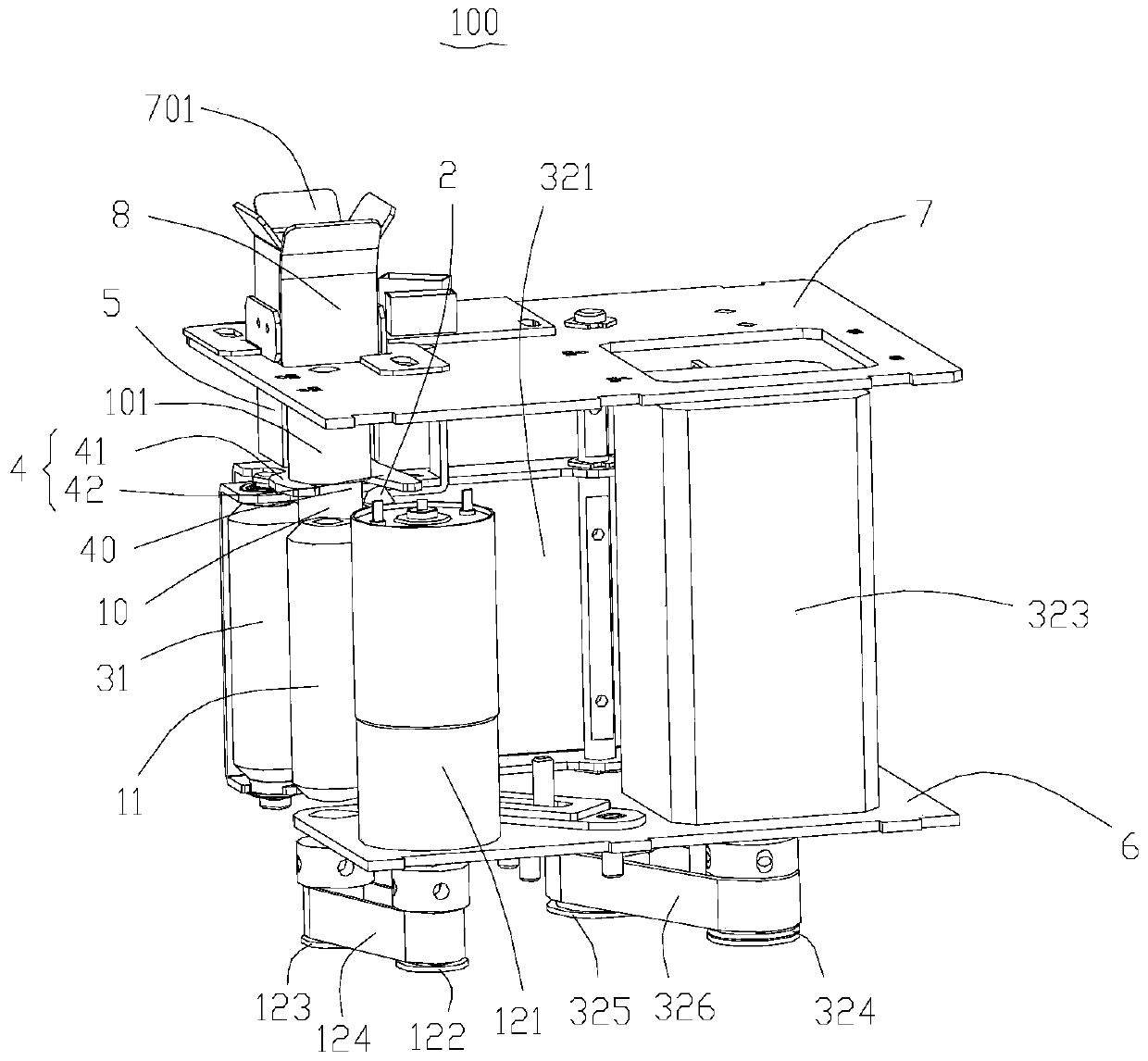
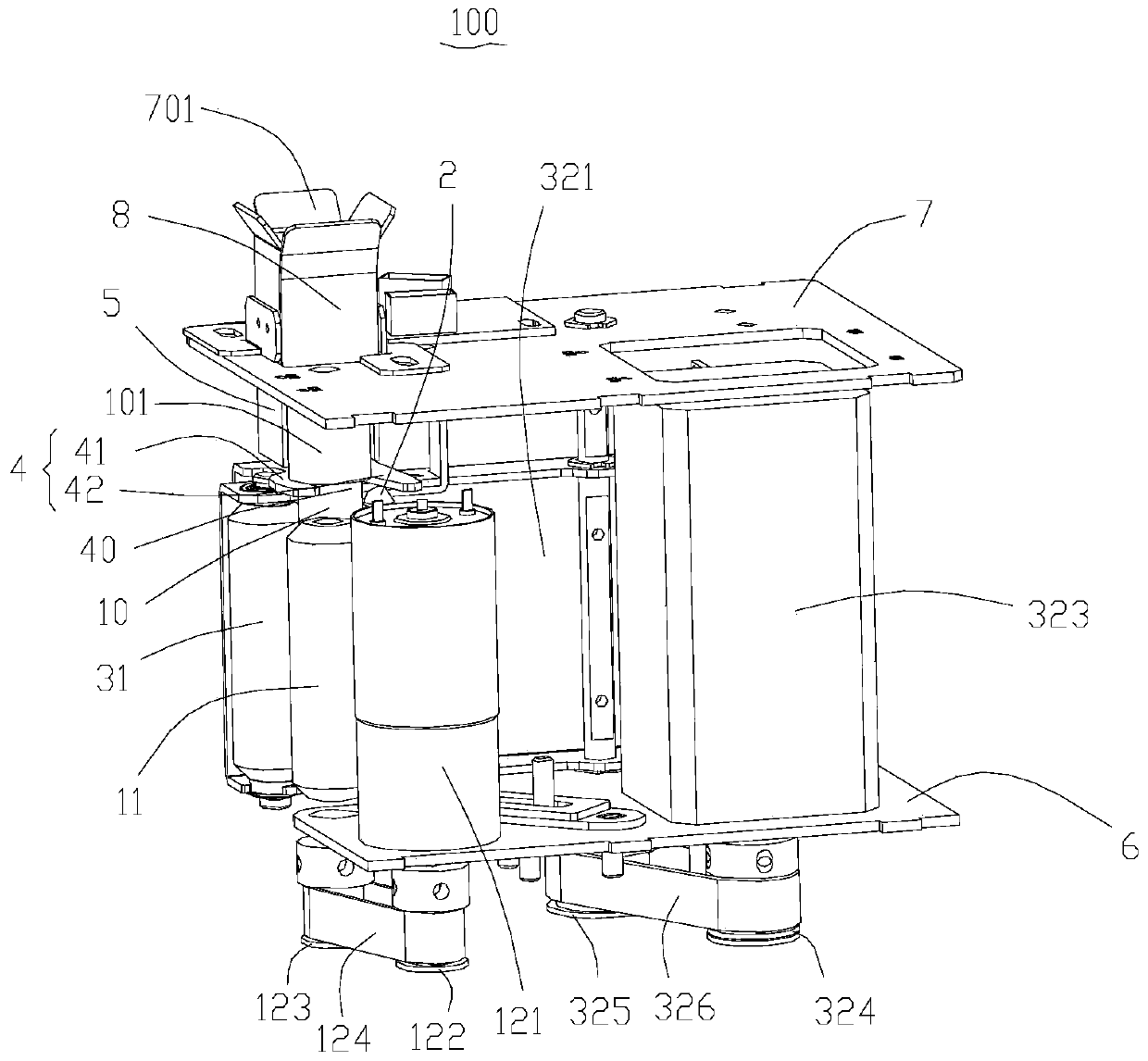
The invention discloses a labeling method of a labeling device, the labeling device and an automatic labeling machine. The labeling method of the labeling device comprises the steps that preliminarilyattaching a label is carried out; a pressing wheel is driven to loosen a test tube so that a gap can exist between a driving wheel and the test tube, meanwhile, a positioning part still positions thetest tube, the driving wheel is stopped, the label feeds paper into the gap between the test tube and the driving wheel, when the head end of the label paper enters the gap, the pressing wheel is driven to slowly press the test tube, the head of the label paper and the driving wheel so that the head of the label paper can be flatly attached to the test tube; and label clinging is carried out, thepressing wheel is driven to press the test tube tightly, so that the label clings to the test tube under the pressure of the pressing wheel, then the driving wheel rotates while the label paper continuously feeds the paper, and the test tube is driven by the driving wheel to completely cling the label paper to the test tube. According to the labeling method of the labeling device, wrinkles can beavoided when one side of the label is not completely adhered to the test tube during labeling of the test tube.

Description

technical field [0001] The invention relates to the field of test tube labeling, in particular to a labeling method of a labeling device, a labeling device and an automatic labeling machine. Background technique [0002] In medical institutions such as hospitals, when patients undergo physical examinations, test tubes are required to store the collected body fluids, and each test tube needs to be labeled to identify each examination of each patient. In the past, medical staff were required to label test tubes one by one, which was inefficient and error-prone. The test tube labeling machine is used to automatically label the test tubes. However, when labeling the test tubes, the test tubes are clamped between the driving wheel, the driven wheel and the pressure wheel, and the driving wheel is driven to rotate to drive the test tubes to rotate. The above printing label mechanism outputs the label, one side of the label sticks to the test tube, and the label rotates with the te...

Claims


Application Information

Patent Timeline
IPC IPC(8): B65C9/06B65C9/04B65C9/30B65C3/16
CPCB65C3/16B65C9/04B65C9/06B65C9/30
Inventor 辛奇功
Owner 智门子(深圳)科技有限公司
Why Eureka
Try Eureka