Induction type automatic paving machine

A paver and inductive technology, applied in the field of inductive automatic pavers, can solve problems such as tipping, affecting throwing accuracy and throwing quality, riprap bucket offset, etc., to achieve flexible operation and improve riprap Efficiency and smooth lifting operation

Active Publication Date: 2020-05-08
CCCC SHANGHAI DREDGING
View PDF5 Cites 3 Cited by
  • Summary
  • Abstract
  • Description
  • Claims
  • Application Information

AI Technical Summary

Problems solved by technology

This patent can effectively increase the construction continuity of the riprap for breakwater bottom protection and improve construction efficiency. However, when the riprap bucket is hoisted by a sling, it is prone to shifting and tipping of the riprap bucket during throwing, which affects the throwing accuracy and throwing effect. set quality

Method used


Image

  • Induction type automatic paving machine
  • Induction type automatic paving machine
  • Induction type automatic paving machine

Examples


Embodiment 1

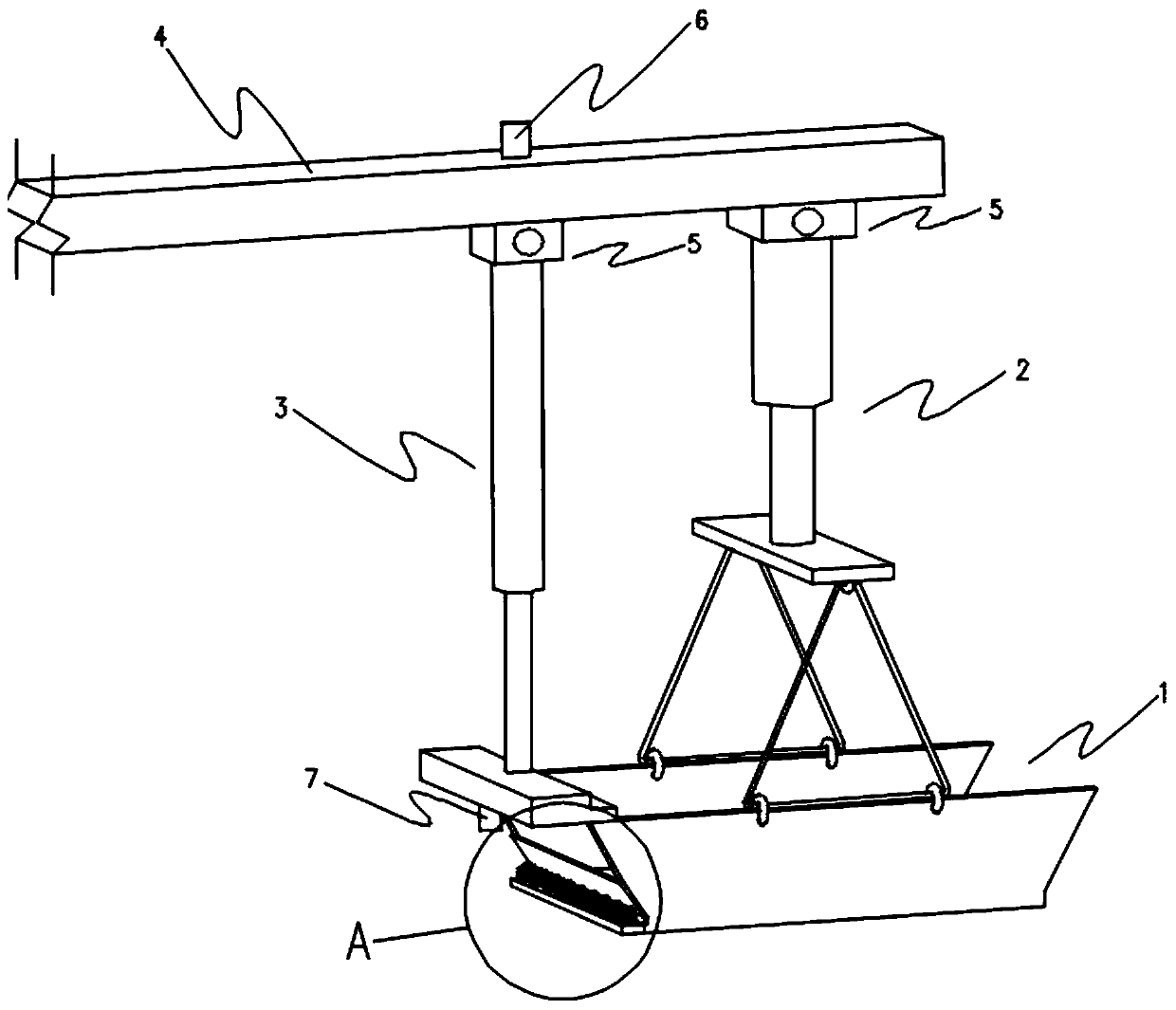
[0046] as attached figure 1 As shown, an induction type automatic spreader includes a boom 4, a bucket 1, a lifting component 2, a tipping component 3 and a positioning component, and the lifting component 2 and the tipping component 3 are all arranged in the on the boom 4.

[0047] The hanging bucket 1 is an open structure, and the hanging bucket 1 is fixed on the hanging arm 4 through the hoisting assembly 2 .

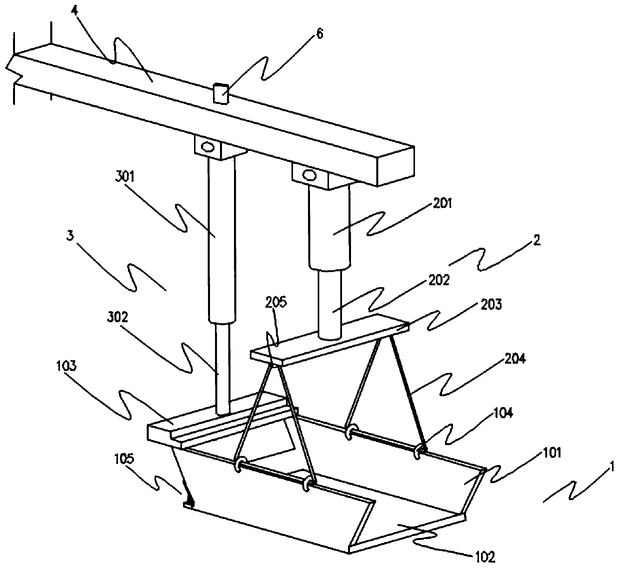
[0048] as attached image 3 As shown, the hanging bucket 1 includes a side plate 101 , a bottom plate 102 and a hanging plate 103 .

[0049] The side plate 101 includes a first side plate 101 and a second side plate 101, the first side plate 101 and the second side plate 101 are respectively fixed on opposite sides of the bottom plate 102, and the hanger plate 103 is fixed on the The upper part of the side plate 101 is fixedly connected with the first side plate 101 and the second side plate 101 respectively.

[0050] Preferably, the first side plate 101 and the ...

Embodiment 2

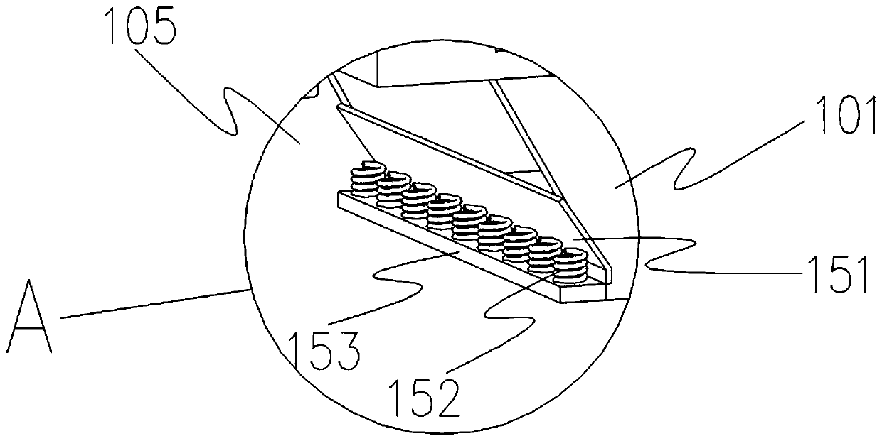
[0073] Based on the above-mentioned Embodiment 1, the similarities will not be repeated, and the differences are as follows: Figure 5 and 6 As shown, the number of the tilting assemblies 3 is a group, and each of the tilting assemblies 3 is located on opposite sides of the bucket 1 respectively; the number of the stopper assemblies 105 is a group, and each The stopper assemblies 105 are respectively located on opposite sides of the bucket 1 . On the one hand, the bucket 1 can be tipped and thrown in two directions, and on the other hand, the bucket 1 can be transported smoothly and the stability of the equipment operation can be improved.

[0074] When throwing rocks, the tipping assembly 3 on one side of the bucket 1 drives the second telescopic rod 302 to shrink, and the tipping assembly 3 on the other side drives the second telescopic rod 302 to extend, so that the bucket 1 rotates around the lifting ring 205 to realize the lifting The inclination of the bucket 1 causes ...


PUM


Abstract

The invention relates to an induction type automatic paving machine. The induction type automatic paving machine comprises a lifting arm, a lifting bucket, a lifting assembly, a tipping assembly and apositioning assembly; the lifting assembly and the tipping assembly are all arranged on the lifting arm; the lifting bucket is of an open structure, and the lifting bucket comprises a side plate, a bottom plate and a lifting plate; the lifting bucket is fixed to the lifting arm through the lifting assembly; and the positioning assembly comprises a GPS position finder and a distance monitor. According to the induction type automatic paving machine, the defects that riprap is uneven, local missing is happened, local stacking is high, supplement riprap is need to be carried out repeatedly and the construction cost is increased due to the fact that existing riprap equipment is prone to being affected by human or environmental factors are overcome. The induction type automatic paving machine is simple in structure, flexible in operation, stable in lifting operation, can avoid the occurrence of lifting bucket deviation and tipping, is conducive to accurate riprap positioning, improving theriprap accuracy, improving the qualified rate of riprap section forming of a dam body, reducing the construction cost, and improving the construction quality and efficiency.

Description

technical field [0001] The invention involves the field of stone throwing equipment technology, specifically a sensor automatic pavement. Background technique [0002] In recent years, my country's waterway engineering construction has developed vigorously. With the continuous deepening of the construction of the Yangtze River Golden Waterway Project, the scale and number of Yangtze River waterway regulation projects have continued to increase. Major breakthroughs have been made in the construction of the Yangtze River Waterway Regulation Project. More and more new Technology and construction technology are used and developed in it. [0003] Underwater throwing is a common underwater underwater protection technology, which is widely used in the construction of the Yangtze River Channel Rectification Project. The underwater riprap project of the Yangtze River waterway improvement project mainly has several uses such as slope protection, foot protection, bottom protection, and...

Claims


Application Information

Patent Timeline
Patent Type & Authority Applications(China)
IPC IPC(8): E02D15/10
CPCE02D15/10E02D2600/10
Inventor 杨杰王铮李东鹏林晓辉嵇文远
Owner CCCC SHANGHAI DREDGING
Why Eureka
Try Eureka