Mould plate for forming groove of inspection chamber

A technology for stereotyped templates and inspection wells, which is applied to waterway systems, sewer systems, drainage structures, etc., can solve the problem of low mold versatility, and achieve the effect of improving mold versatility and reducing costs

Pending Publication Date: 2020-05-08
POWERCHINA WATER ENVIRONMENT GOVERANCE +1
View PDF0 Cites 0 Cited by
  • Summary
  • Abstract
  • Description
  • Claims
  • Application Information

AI Technical Summary

Problems solved by technology

[0003] The purpose of the present invention is to provide an inspection well launder shaping template, which aims to solve the technical problem of low mold versatility in the prior art that different types of inspection well launders require multiple sets of molds to be processed

Method used


Image

  • Mould plate for forming groove of inspection chamber
  • Mould plate for forming groove of inspection chamber
  • Mould plate for forming groove of inspection chamber

Examples


Embodiment approach

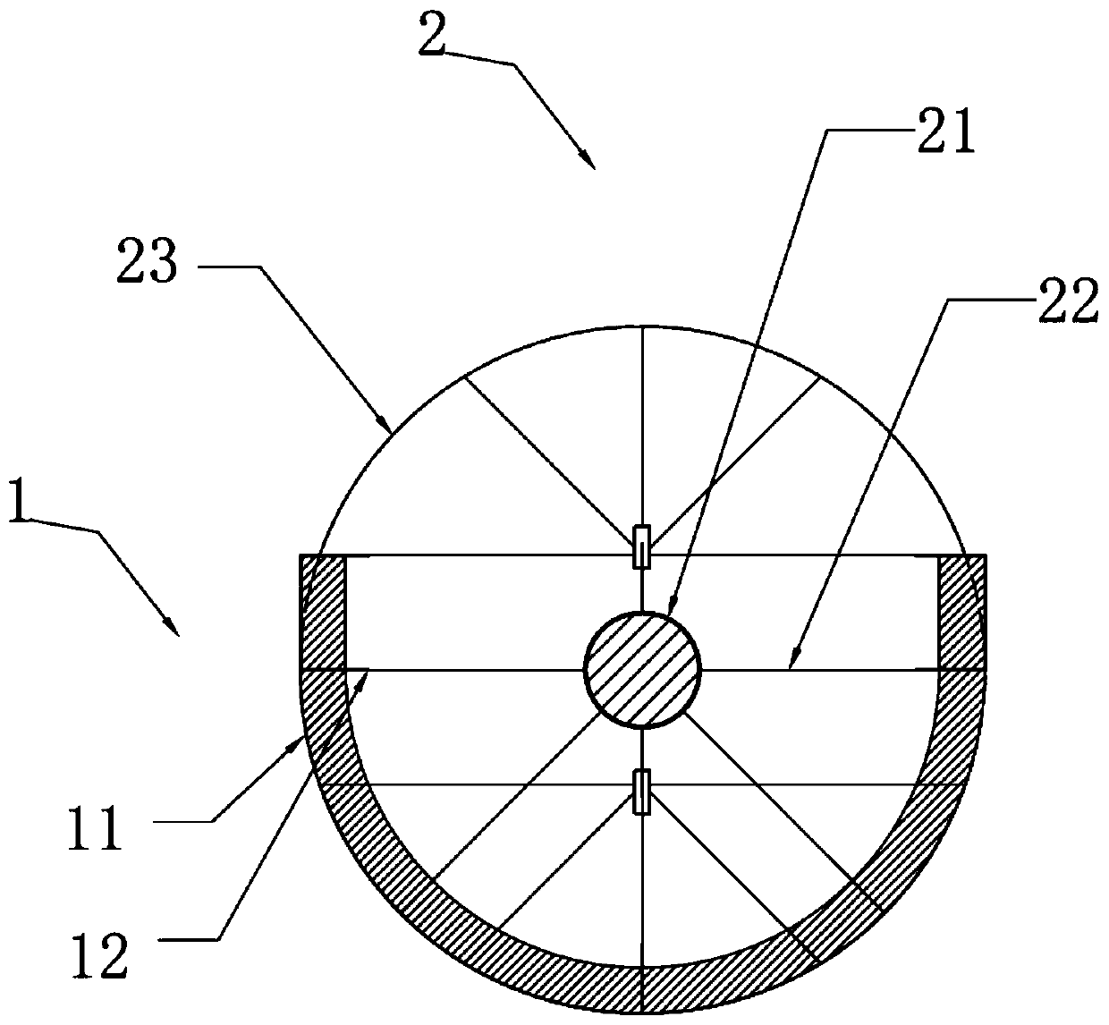
[0033] figure 1 It is a schematic cross-sectional view of the local structure of the shaped template of the inspection well launder in the embodiment of the present invention, as figure 1 As shown, in this embodiment, the inspection well launder shaping template includes a mold assembly 1 that can be matched and combined according to the launder type. According to different inspection well types, the launder types are also different, such as rainwater inspection wells and sewage The width of the top of the corresponding chute is designed differently for inspection wells; for two-way inspection wells, three-way inspection wells, and four-way inspection wells of different sizes, the bending radius of the corresponding launder turns is also different. The shape of the mold assembly 1 is a unified standardized shape formed according to the different types, pipe diameters, angles, etc. of the launder. The standardization here refers to the conventional dimensions stipulated in the ...

Embodiment 1

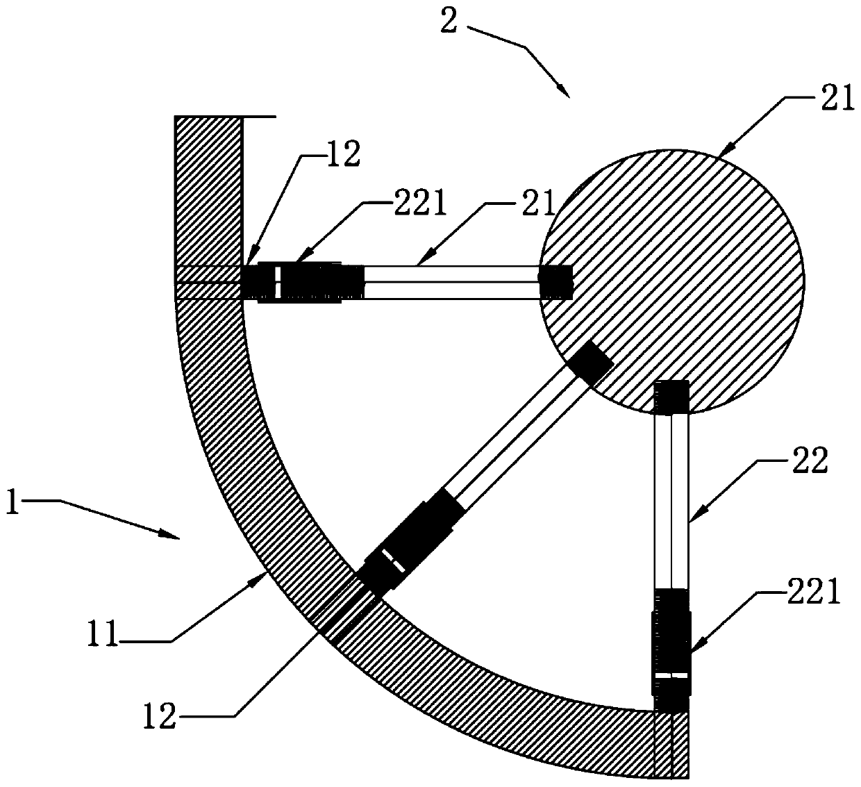
[0051] Figure 4 It is a schematic structural view of the shaped template of the inspection well launder in Embodiment 1 of the present invention, as Figure 4 As shown, the nominal diameter of the drainage pipe in the inspection well is DN300㎜, the chute of the inspection well is a linear chute, the bracket assembly 2 includes a central axis 21, and the mold assembly 1 is composed of two symmetrically combined arc-shaped panels. Other numbers of combination templates 11 can be used for splicing, and here only two of them are taken as an example for illustration, and no unique limitation is made.

[0052] Such as Figure 6 As shown, optionally, the thickness of each curved panel is 20mm, and the formwork column flute 12 embedded on each curved panel is a cylinder with a diameter of 10mm and a total length of 30mm, wherein the formwork column flute 12 faces The height of the convex part inside the curved surface is 10 mm. The diameter of the central axis 21 is preferably 80 ...

Embodiment 2

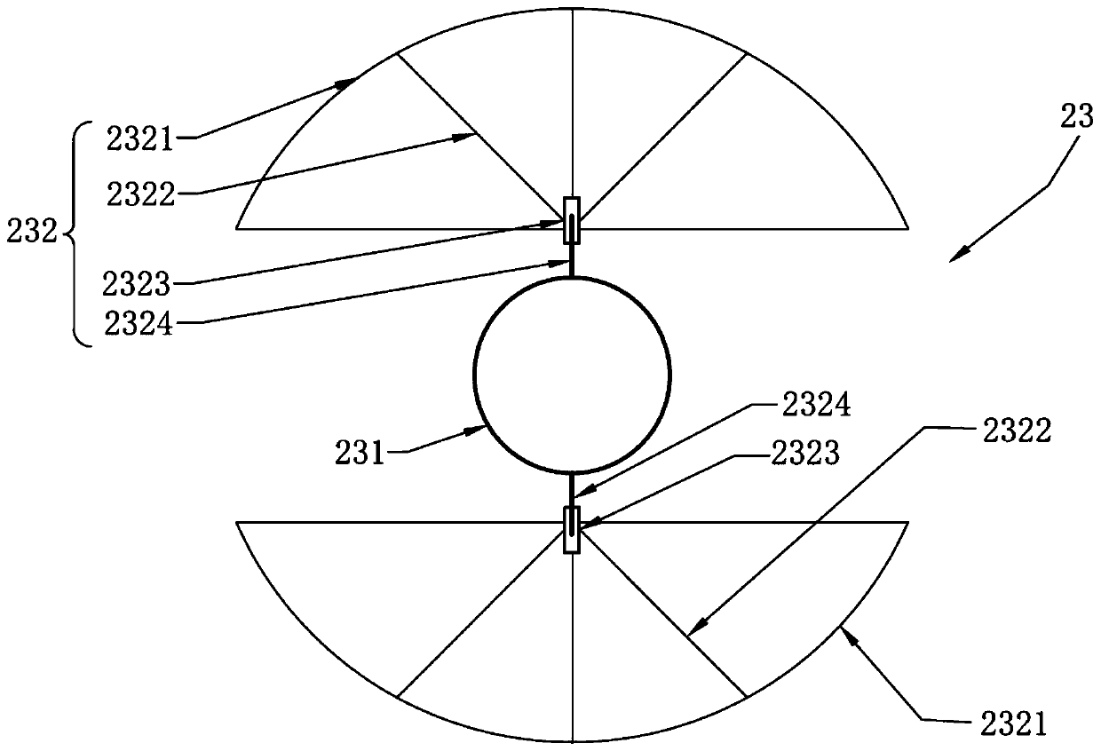
[0058] Such as Figure 7 As shown, in this embodiment, the nominal diameter of the drainage pipe in the inspection well is DN300mm, and the launder in the inspection well is a 90° three-way launder. Compared with Embodiment 1, the drainage pipe in the inspection well in this embodiment is composed of two water inlets and one water outlet converging, and the water inlet and water outlet intersect at 90°. The mold assembly 1 of the shaped template of the launder in this embodiment is composed of a plurality of combined templates 11, including a straight panel formed at the straight line of the launder and an arc-shaped panel formed at the turning of the launder. The bracket assembly 2 is provided with two central shafts 21, one long central shaft is supported by the shaft end jacking assembly 23 placed at the two water inlets, and one end of the short central shaft is supported by the shaft end jacking assembly placed at the water outlet. 23 supports, the other end of the short...


PUM


Abstract

The invention relates to the technical field of piping construction and discloses a mould plate for forming a groove of an inspection chamber. The mould plate comprises a mould assembly capable of performing matching assembly according to groove types and a supporting frame assembly capable of performing matching assembly according to the mould assembly so as to fix and support the mould assembly.The mould assembly is in detachable connection with the supporting frame assembly. The mould assembly forms a uniform and standard shape against different groove types, pipe diameters, angles and soon, so that based on the technical scheme of the groove forming mould plate, the mould assembly and the supporting frame assembly can be quickly matched and assembled according to the type of the groove to be processed during construction. Compared to traditional wooden mould plates, the mould plate for forming a groove of an inspection chamber can be quickly assembled, the universality of the mould is improved, cost is reduced and the quality of the formed groove is more in line with requirements of standard specifications.

Description

technical field [0001] The invention relates to the technical field of pipeline construction, and more specifically relates to a shaped formwork for an inspection well flow tank. Background technique [0002] During the construction of the drainage pipeline, the drainage pipeline inspection well is the main structure in the outdoor drainage system. It mainly plays the role of convenient inspection and cleaning of the pipeline. Variable diameter and other special functions. In order to make the water flow smoothly, generally a trough for flowing water is set in the inspection well, that is, the launder. One of the existing launder forming methods is to build it according to the drawings and atlases, that is, to use brick masonry to form it; the other is to cast in-situ Forming, that is, concrete pouring and forming on site after the arc-shaped wooden formwork is erected. In the existing launder forming method, the brick launder has a short service life and is easy to be dam...

Claims


Application Information

Patent Timeline
Patent Type & Authority Applications(China)
IPC IPC(8): E03F5/02E03F3/06
CPCE03F3/06E03F5/02
Inventor 王寒涛王仲禹潘志坤张广平张正武王飞跃张广星
Owner POWERCHINA WATER ENVIRONMENT GOVERANCE
Why Eureka
Try Eureka