Lifting tool for sheared-off continuous oil tube and using method
A technology of oil pipes and tools, which is applied in the field of tight gas field exploitation, can solve the problems of complicated process and high safety risk, and achieve the effects of reduced safety risk, improved construction efficiency and high tensile strength
- Summary
- Abstract
- Description
- Claims
- Application Information
AI Technical Summary
Problems solved by technology
Method used
Image
Examples
Embodiment 1
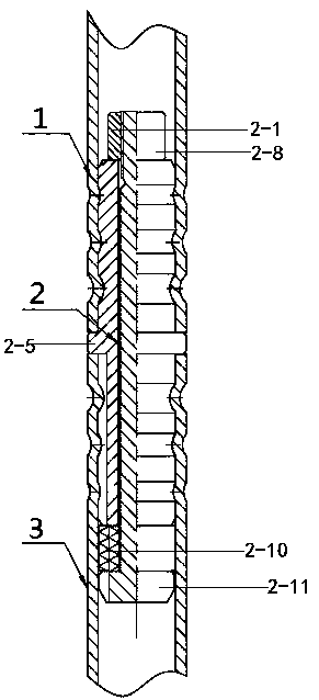
[0024] Such as figure 1 and figure 2 As shown, a lifting tool for cut coiled tubing includes a mandrel 2-8, the mandrel 2-8 is covered with a rolling groove, and the mandrel 2-8 below the rolling groove is covered with a sealing rubber cylinder 2- 10. The mandrel 2-8 above the rolling groove is covered with a pressing piece, and the bottom end of the mandrel 2-8 is connected with a stud head 2-11.
[0025] The pressing part is a nut 2-1, and the mandrel 2-8 is provided with threads matching the nut 2-1.
[0026] The outer diameter of the stud head 2-11 is larger than the outer diameter of the sealing rubber cylinder 2-10.
[0027] The bottom end of the mandrel 2-8 is connected with a stud head 2-11, the outer diameter of the stud head 2-11 is longer than that of the sealing rubber cylinder 2-10, and the bottom of the sealing rubber cylinder 2-10 falls on the stud head 2-11 surface, so that when the sealing rubber cylinder 2-10 is squeezed, the bottom of the sealing rubber ...
Embodiment 2
[0029] Such as figure 1 and figure 2 As shown, on the basis of Embodiment 1, a limiting boss 2-5 is connected in the middle of the rolling groove, and the rolling groove is divided into an upper rolling groove and a lower rolling groove by the limiting boss 2-5.
[0030] The upper rolling groove includes a first rolling groove 2-2, a second rolling groove 2-3 and a third rolling groove 2-4 from top to bottom, the first rolling groove 2-2, the second rolling groove The groove depths of rolling groove 2-3 and the third rolling groove 2-4 are gradually deepening.
[0031] The lower rolling groove includes the fourth rolling groove 2-6, the fifth rolling groove 2-7 and the sixth rolling groove 2-9 from top to bottom, the fourth rolling groove 2-6, the fifth rolling groove Rolling groove 2-7 and the 6th rolling groove 2-9 groove depth are progressively deepening type.
[0032] The limiting boss 2-5, the upper rolling groove and the lower rolling groove are integrally formed.
...
Embodiment 3
[0037] Such as figure 1 and figure 2 Shown, on the basis of embodiment 2, a kind of use method of the lifting tool that has cut coiled tubing may further comprise the steps:
[0038] The first step is to dock with the coiled tubing 3, and insert the end of the lifting tool 2 with the stud head 2-11 downward into the upper end of the coiled tubing 3 of the natural gas wellbore until the limit boss 2-5 withstands the coiled tubing 3 The end of the lifting tool 2 with the stud head 2-11 is lowered into the wellbore until the limit boss 2-5 withstands the port of the coiled tubing 3 that should be lifted below the lifting tool 2.
[0039] The second step is to roll the coiled tubing 3, using a rolling tool to roll the coiled tubing 3 to the fourth rolling groove 2-6, the fifth rolling groove 2-7 and the sixth rolling groove 2-9 in sequence Top: Roll the upper end of the coiled tubing 3 to the fourth rolling groove 2-6, the fifth rolling groove 2-7 and the sixth rolling groove o...
PUM
 Abstract
Description
Claims
Application Information
 - R&D
- Intellectual Property
- Life Sciences
- Materials
- Tech Scout
- Unparalleled Data Quality
- Higher Quality Content
- 60% Fewer Hallucinations
Browse by: Latest US Patents, China's latest patents, Technical Efficacy Thesaurus, Application Domain, Technology Topic, Popular Technical Reports.
© 2025 PatSnap. All rights reserved.Legal|Privacy policy|Modern Slavery Act Transparency Statement|Sitemap|About US| Contact US: help@patsnap.com


