Diamond wire drying device

A technology of drying device and diamond wire, which is applied in the directions of drying, drying machine, drying gas arrangement, etc., and can solve the problems of low work efficiency and so on

Inactive Publication Date: 2020-05-08
邱昌萍
View PDF8 Cites 2 Cited by
  • Summary
  • Abstract
  • Description
  • Claims
  • Application Information

AI Technical Summary

Problems solved by technology

[0005] In order to overcome the shortcomings of low work efficiency due to the design of the drying machine, only a part of the diamond wire can be dried at...

Method used


Image

  • Diamond wire drying device
  • Diamond wire drying device
  • Diamond wire drying device

Examples


Embodiment 1

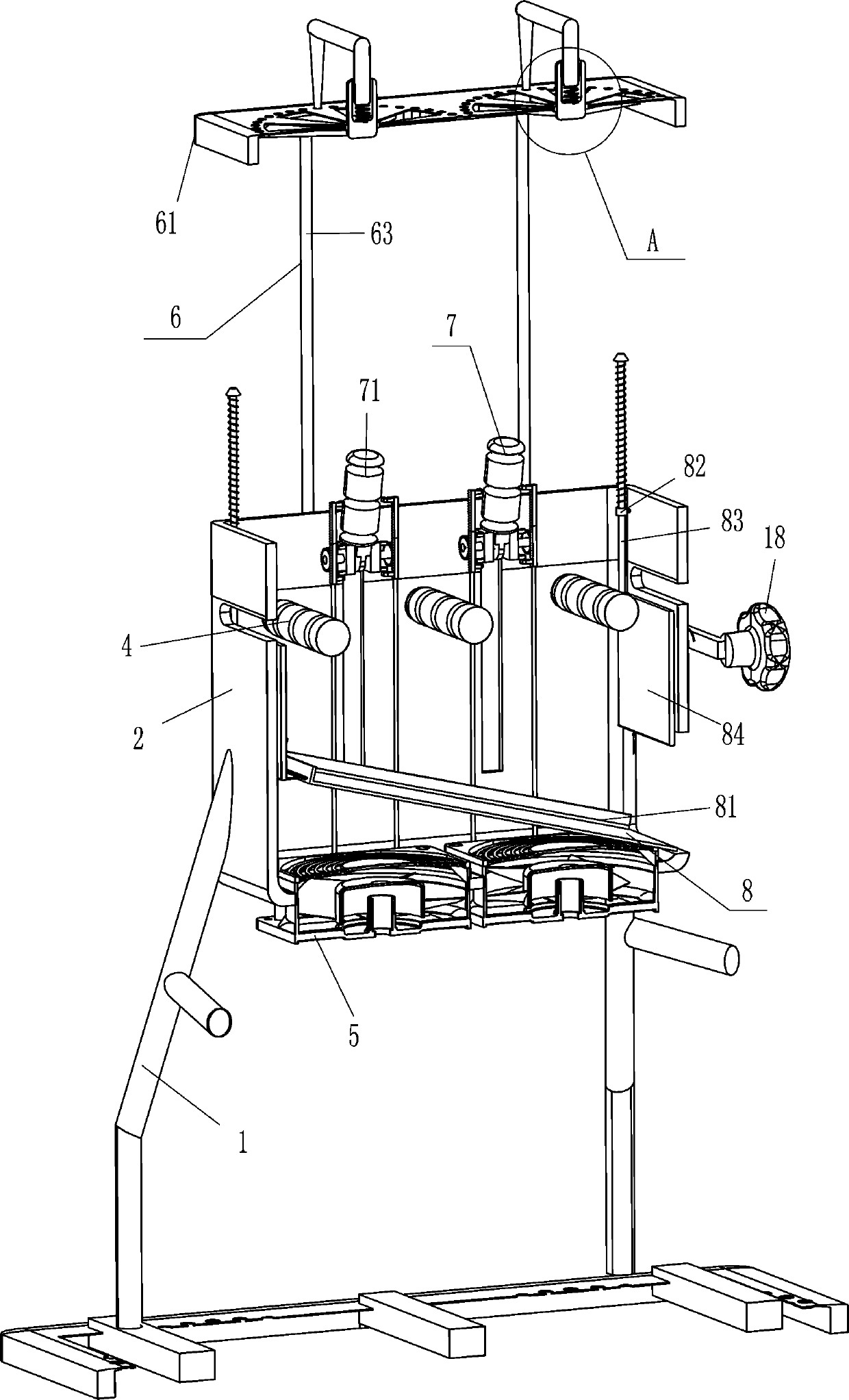
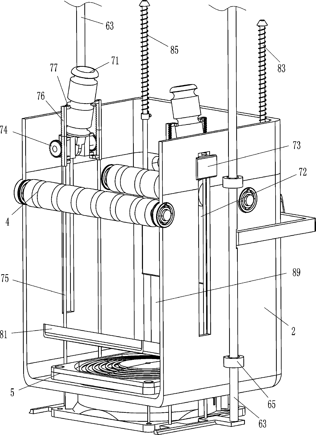
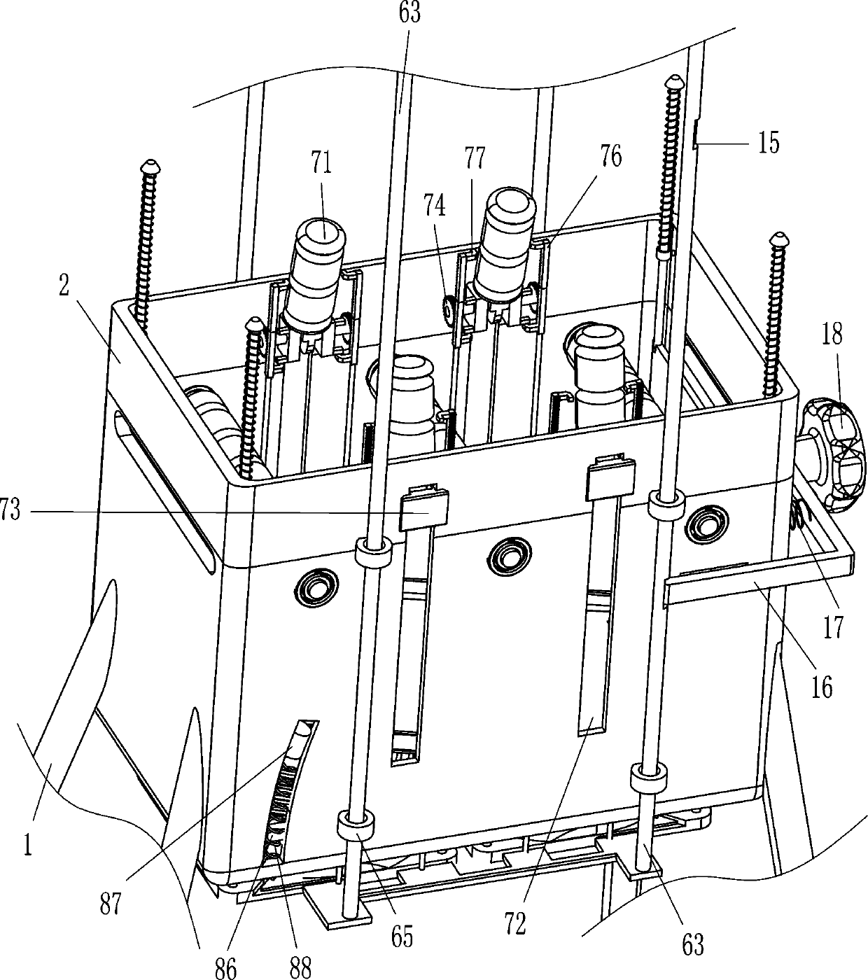
[0021] see Figure 1-Figure 4 , a diamond wire drying device, including a support frame 1, a frame body 2, a roller 4, a heat fan 5, a driving mechanism 6 and a pushing mechanism 7, a frame body 2 is installed between the top ends of the support frame 1, and the frame body 2 A heat fan 5 is installed between the bottoms, a driving mechanism 6 is arranged between the front and rear sides outside the frame body 2, and a pushing mechanism 7 that can move the diamond wire is provided in the frame body 2, and the pushing mechanism 7 cooperates with the driving mechanism 6, and the frame Body 2 has openings 3 on the left and right sides, and rollers 4 are installed on the front and rear sides of the frame body 2 in a rotating manner, and the rollers 4 cooperate with the pushing mechanism 7 .

[0022] The driving mechanism 6 includes a cover plate 61, a movable rod 63, a fixed plate 64 and a guide sleeve 65. The outer, front, and rear sides of the frame body 2 are symmetrically equip...

Embodiment 2

[0028] see Figure 2-Figure 4 Compared with Embodiment 1, the main difference of this embodiment is that in this embodiment, a blocking mechanism 8 is also included, and the blocking mechanism 8 includes a swing plate 81, a guide sleeve 82, a sliding rod 83, a baffle plate 84, and a first spring 85 , sliding block 87 and the second spring 88, the frame body 2 has arc groove 86 on the left side of the lower part of the front and rear sides, the sliding type in the arc groove 86 is provided with sliding block 87, the bottom of sliding block 87 and arc groove 86 A second spring 88 is connected between the bottom, and a swing plate 81 is fixedly connected between the inner surfaces of the sliding blocks 87 on the front and rear sides. A guide sleeve 82 is installed symmetrically on the left and right sides of the body 2, and a sliding rod 83 is provided in the guide sleeve 82. A baffle plate 84 is fixedly connected between the bottom ends of the two slide rods 83, and the baffle p...

Embodiment 3

[0031] see figure 1 , 2 , 4 and Figure 5 , compared with embodiment 1 and embodiment 2, the main difference of this embodiment is that this embodiment also includes a hollow shaft 9, a T-bar 10, an insertion rod 11, a movable plate 13 and a third spring 14, and a cover plate 61 The middle parts of the left and right sides are rotatably connected with a hollow shaft 9, and the hollow shaft 9 is slidably provided with a T-shaped bar 10, and a third spring 14 is connected between the bottom end of the T-shaped bar 10 and the inner bottom of the hollow shaft 9. The front and rear ends of the type rod 10 are fixedly connected with inserting rods 11, and the left and right sides of the top of the cover plate 61 are evenly spaced with jacks 12, and the inserting rods 11 are located in the jacks 12 to cooperate with them, and the bottom ends of the hollow shaft 9 are evenly spaced. A movable plate 13 is fixedly connected, and the movable plate 13 cooperates with the through hole 62...


PUM


Abstract

The invention relates to a drying device, in particular to a diamond wire drying device. According to the diamond wire drying device, more diamond wires can be dried simultaneously, and the working efficiency is improved. The diamond wire drying device comprises a supporting frame, a frame body, hot air fans, a driving mechanism, a pushing mechanism and the like; the frame body is installed amongthe top ends of the supporting frame, the hot air fans are installed in the bottom of the frame body, the driving mechanism is arranged on the position, between the front side face and the rear side face of the frame body, outside the frame body, the pushing mechanism capable of enabling the diamond wires to move is arranged in the frame body, and the pushing mechanism is matched with the drivingmechanism. According to the diamond wire drying device, a diamond wire penetrates through openings, and a cover plate is pushed, so that guide rollers make contact with the diamond wire to enable thediamond wire to move downwards, more diamond wire is moved into the frame body, the hot air fan is started, the diamond wire can be dried, and the working efficiency is improved.

Description

technical field [0001] The invention relates to a drying device, in particular to a diamond wire drying device. Background technique [0002] Diamond wire saw, also known as diamond wire, refers to the use of electroplating or resin bonding methods to fix diamond abrasives on metal wires. During the production of diamond wires, sanding is required, but after diamond wires are sanded, diamond wires need to be sanded. The wire is dried so that the diamond wire can be processed in the next step. [0003] Existing diamond wire drying devices, such as the Chinese patent with patent announcement number CN207945940U disclose a drying oven for diamond wire production equipment, including a box body, an upper cover and a metal heat dissipation plate; the heat dissipation plate is embedded in the box Inside, and flush with the top surface of the box; the upper cover is hinged with the box to cover the top surface of the box; the center of the heat sink is provided with a groove for d...

Claims


Application Information

Patent Timeline
IPC IPC(8): F26B13/10F26B21/00F26B25/00
CPCF26B13/10F26B21/001F26B25/00
Inventor 邱昌萍
Owner 邱昌萍
Why Eureka
Try Eureka