
Space geometry automatic measurement method based on laser ranging

A laser ranging and geometric measurement technology, applied in the field of) measurement, can solve the problems of geometric parameters (distance, area, volume cannot be directly measured, large accidental errors of instruments, large environmental restrictions, etc., to expand the measurement range and measurement range, The effect of reducing the workload of measurement and getting rid of measurement limitations

Inactive Publication Date: 2020-05-08
SOUTHWEAT UNIV OF SCI & TECH
View PDF8 Cites 8 Cited by
  • Summary
  • Abstract
  • Description
  • Claims
  • Application Information

AI Technical Summary

Problems solved by technology

Both have good ranging effects, but there are also some deficiencies worth improving
[0004] First, the above-mentioned instruments mainly measure the distance from the instrument to the target point, and cannot directly measure the geometric parameters (distance, area, volume, etc.) between multiple target points that the operator cannot reach, and are greatly restricted by the environment
Second, the above-mentioned instruments are mainly aimed at the measurement of one-dimensional distances, and can simply measure the area of ​​a rectangle and the volume of a cube, but cannot complete the measurement of two-dimensional and three-dimensional spatial parameters (area and volume) of other shapes
Third, due to the hand-held operation during measurement, the above-mentioned instruments have large accidental errors

Method used


Image

  • Space geometry automatic measurement method based on laser ranging
  • Space geometry automatic measurement method based on laser ranging
  • Space geometry automatic measurement method based on laser ranging

Examples


Embodiment Construction

[0014] The present invention is described in detail with an example as follows.

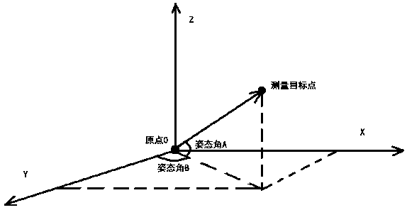
[0015] The main part of the example device of the present invention is as figure 1 As shown, it includes omni-directional rotating gimbal, gimbal drive motor, laser ranging module, electronic compass, camera and computer (not shown in the figure).

[0016] Described cloud platform is divided into vertical rotation part and horizontal rotation part and base, and laser ranging module, electronic compass are positioned on the vertical rotation part of cloud platform, and described camera is positioned at the platform base; Cloud platform base remains static; The straight line where the laser beam from the module passes through the center of rotation of the platform, the camera is fixed on the base, and the positions of the laser ranging module and the gyroscope are relatively fixed; the drive motor is divided into horizontal and vertical drive motors, vertical drive motor and The horizontal driving...


PUM


Abstract

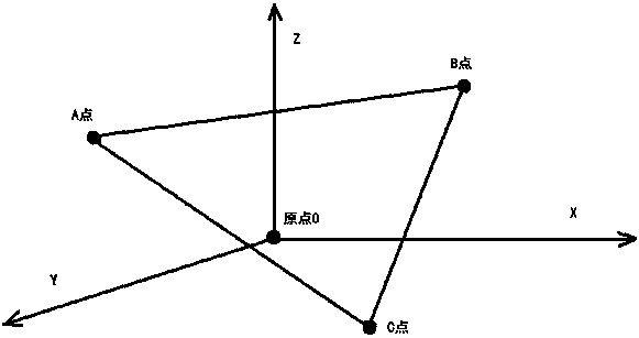
The invention discloses a space geometry automatic measurement method based on laser ranging. The method mainly relates to an omnibearing rotation holder, a laser ranging module, an attitude sensor, arotation driving device, a camera and a control center. The rotation driving device can drive the holder to rotate in all directions and drive the laser ranging module to rotate so as to establish aspatial three-dimensional coordinate system, and spatial coordinate positioning can be achieved on feature points (points capable of reconstructing a spatial geometric figure) of the spatial geometricfigure to be measured in combination with measured attitude parameters and distance parameters; then detailed parameters can be calculated through spatial geometric operation, and actual measurementrequirements are met; the control center enables laser spots to automatically and sequentially coincide with the feature points of the to-be-measured figure through feedback control of the camera, andthen automatic dotting measurement is achieved. Through the above mode, convenient, rapid, automatic and safe measurement of various geometric parameters in a complex environment, a dangerous environment or a special environment which cannot be reached directly and the like can be realized.

Description

technical field [0001] The invention relates to the field of measurement of spatial geometric parameters (distance, area, volume, etc.), especially the measurement method and device in special environments such as complex environments, dangerous environments, or inaccessible environments. Background technique [0002] Due to the good characteristics of laser energy focusing, electromagnetic wave reflection, and high coherence, laser technology has begun to be used in some distance or length measurements at home and abroad. Two common measurement principles are the pulse method and the phase method. Compared with the pulse method, the phase method has a longer measurement time and higher accuracy. According to the phase method of laser ranging, the measurement accuracy of the existing laser ranging modules in the market has reached 1mm. At present, representative laser ranging products on the market include handheld laser rangefinders and telescope rangefinders, with a range...

Claims


Application Information

Patent Timeline
Patent Type & Authority Applications(China)
IPC IPC(8): G01B11/00G01B11/02G01B11/06G01B11/26G01B11/28
CPCG01B11/002G01B11/02G01B11/0608G01B11/26G01B11/28
Inventor 王坤朋姚娟张镠唐齐鸿刘忠仁张江梅冯兴华
Owner SOUTHWEAT UNIV OF SCI & TECH
Learn More