Leakage-proof detection device for valve machining

A leak-proof detection and valve technology, applied in measuring devices, by detecting the appearance of fluid at the leak point, mechanical valve testing, etc., can solve problems such as reducing the practicability of the device, failing to detect valve leaks, and not simulating water flow impact detection, etc. , to achieve the effect of improving the fixed effect and improving the accuracy

Inactive Publication Date: 2020-05-08
广州迅磊科技有限公司
View PDF0 Cites 4 Cited by
  • Summary
  • Abstract
  • Description
  • Claims
  • Application Information

AI Technical Summary

Problems solved by technology

[0003] In the production process of valves, the last process is to carry out leak-proof testing on valves, but there are still the following deficiencies in the current leak-proof testing of valves: the valve will be hit by a large water flow in actual use, but the current The detection device does not simulate the appropriate water flow impact detection, and cannot accurately detect the leakage of the valve, which reduces the practicability of the device

Method used


Image

  • Leakage-proof detection device for valve machining
  • Leakage-proof detection device for valve machining
  • Leakage-proof detection device for valve machining

Examples


Embodiment 1

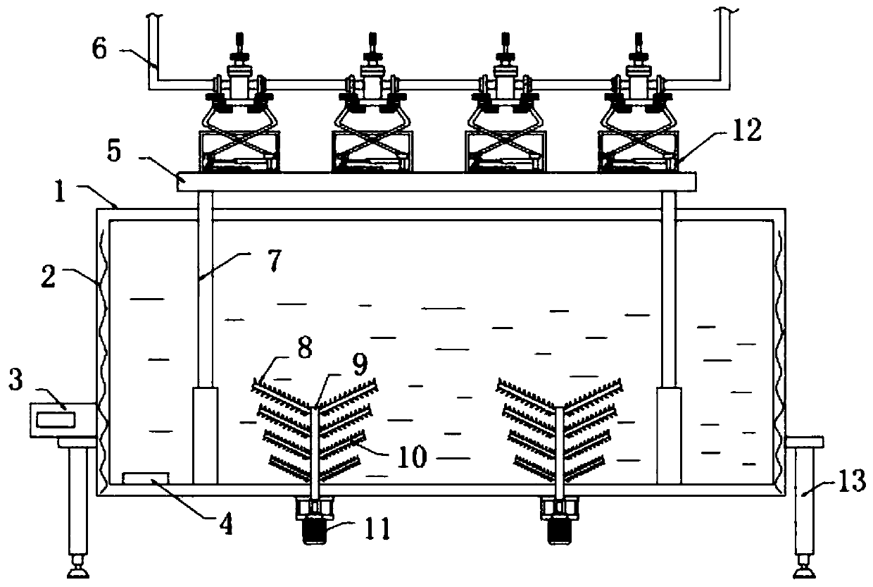
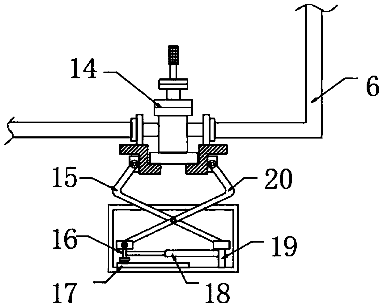
[0029] refer to Figure 1-4 , a leak-proof detection device for valve processing, including a transparent detection box 1, a motor 11 is fixed on both sides of the bottom outer wall of the transparent detection box 1 by screws, and the output shaft of the motor 11 is connected with a rotating rod 9 through a coupling , the two sides of the outer wall of the rotating rod 9 are welded with stirring rods 10 equidistantly distributed, and the specifications of the stirring rods 10 are different in size, and the size of the stirring rods 10 gradually decreases from top to bottom, forming an inverted trumpet-like structure, stirring The outer wall of the rod 10 is welded with equidistantly distributed stirring blades 8, and the size of the stirring blades 8 is different. The inner wall of the transparent detection box 1 is provided with a heating mechanism, and both sides of the bottom inner wall of the transparent detection box 1 are fixed by screws. The first hydraulic rod 7.

[...

Embodiment 2

[0037] refer to Figure 5 , a leak-proof detection device for valve processing, also includes a fixed rod 23 fixed on both sides of the inner wall of the transparent detection box 1 by screws, the other end of the fixed rod 23 is fixed with a baffle 22 by screws, and the baffle 22 is Arc structure.

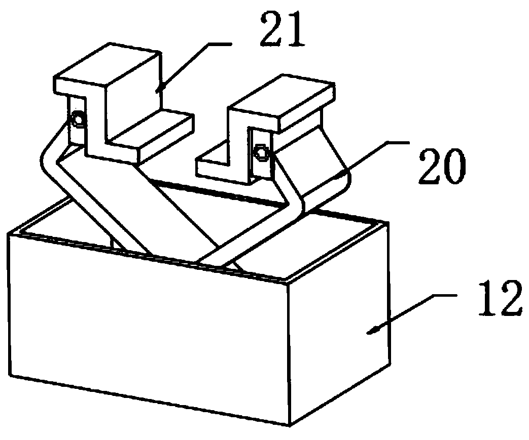
[0038]Connect the equipment to the power supply, connect the first hydraulic rod 7 and the second hydraulic rod 18 to the hydraulic system respectively, adjust the length of the second hydraulic rod 18 according to the specifications of the valve body 14, and make the clamping plate 21 clamp the valve body 14 , connect the air guide tube 6 and the valve body 14 through the flange, adjust the length of the first hydraulic rod 7, make the valve enter the water, ventilate in the air guide tube 6, and wait to see if there are bubbles. If there are no bubbles, turn on the electric heater Wire 2, heat the valve body 14, observe whether the valve body 14 is leaking at high temperature, ...


PUM


Abstract

The invention belongs to the technical field of valve machining, especially relates to a leakage-proof detection device for valve machining. For the problem of the detection accuracy, the following solution is presented: the device comprises a transparent detection box motors are arranged on the two sides of the outer wall of the bottom of the transparent detection box, output shafts of the motorsare connected with rotating rods through couplers, stirring rods distributed at equal intervals are arranged on the two sides of the outer wall of each rotating rod, the specifications and sizes of the stirring rods are different, the sizes of the stirring rods are gradually reduced from top to bottom, and an inverted horn-shaped structure is formed. According to the invention, the motors, the rotating rods, the stirring rods and the stirring blades are arranged; the sizes of the stirring rods are gradually reduced from top to bottom, the inverted horn-shaped structure is formed, the uneven stirring rods can form vortexes and water waves with different sizes, water flow impact with different sizes can be conducted on the valve, the situation that the valve is impacted by water flow can besimulated, and leakage-proof detection can be conducted on the valve more accurately.

Description

technical field [0001] The invention relates to the technical field of valve processing, in particular to a leak-proof detection device for valve processing. Background technique [0002] The valve is a pipeline accessory used to open and close the pipeline, control the flow direction, adjust and control the parameters of the conveying medium. A valve is a device used to control the direction, pressure, and flow of a fluid in a fluid system. It is a device that makes or stops the flow of media (liquid, gas, powder) in piping and equipment and controls its flow. [0003] In the production process of valves, the last process is to carry out leak-proof testing on valves, but there are still the following deficiencies in the current leak-proof testing of valves: the valve will be hit by a large water flow in actual use, but the current The detection device does not simulate a suitable water flow impact detection, and cannot accurately detect the leakage of the valve, which redu...

Claims


Application Information

Patent Timeline
Patent Type & Authority Applications(China)
IPC IPC(8): G01M3/08G01M13/003
CPCG01M3/086G01M13/003
Inventor 夏波
Owner 广州迅磊科技有限公司
Why Eureka
Try Eureka