Eureka AIR delivers breakthrough ideas for toughest innovation challenges, trusted by R&D personnel around the world.

Hydraulic torque converter testing machine provided with track buffer mechanism and capable of being stably pushed

A technology of hydraulic torque converter and buffer mechanism, applied in the field of testing machines, can solve the problems of not setting, the design is not rigorous enough, the transmission mechanism is not stable enough, etc. Effect

Inactive Publication Date: 2020-05-08
上海正源汽车附件有限公司
View PDF0 Cites 0 Cited by
  • Summary
  • Abstract
  • Description
  • Claims
  • Application Information

AI Technical Summary

Problems solved by technology

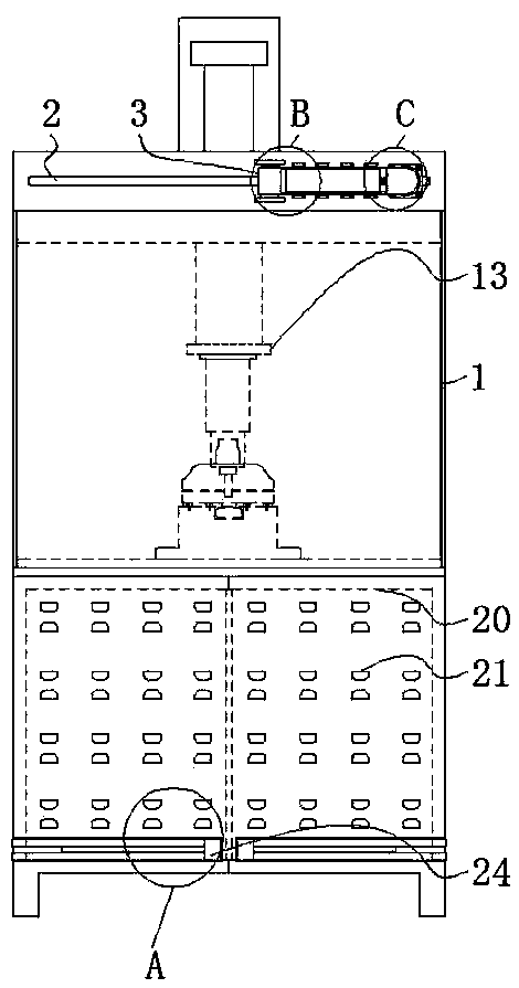
[0004] The purpose of the present invention is to provide a hydraulic torque converter testing machine with a track buffer mechanism that can be pushed smoothly, so as to solve the problem that the existing main body proposed in the background technology is not rigorous enough in the design of the external structure direction. The extra available space leads to the problem that the main body is not practical and convenient when used. At the same time, there is no good protective auxiliary mechanism outside the transmission mechanism inside the main body, which leads to the fact that the transmission mechanism cannot be used when it is in use. There is also the problem of not being stable enough

Method used


Image

  • Hydraulic torque converter testing machine provided with track buffer mechanism and capable of being stably pushed
  • Hydraulic torque converter testing machine provided with track buffer mechanism and capable of being stably pushed
  • Hydraulic torque converter testing machine provided with track buffer mechanism and capable of being stably pushed

Examples


Embodiment Construction

[0027] The following will clearly and completely describe the technical solutions in the embodiments of the present invention with reference to the accompanying drawings in the embodiments of the present invention. Obviously, the described embodiments are only some, not all, embodiments of the present invention.

[0028] In the description of the present invention, unless otherwise stated, the meaning of "plurality" is two or more; the terms "upper", "lower", "left", "right", "inner", "outer" , "front end", "rear end", "head", "tail", etc. indicate the orientation or positional relationship based on the orientation or positional relationship shown in the drawings, and are only for the convenience of describing the present invention and simplifying the description, rather than Nothing indicating or implying that a referenced device or element must have a particular orientation, be constructed, and operate in a particular orientation should therefore not be construed as limiting ...


PUM


Abstract

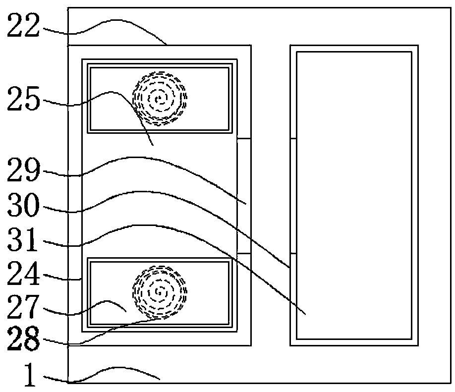
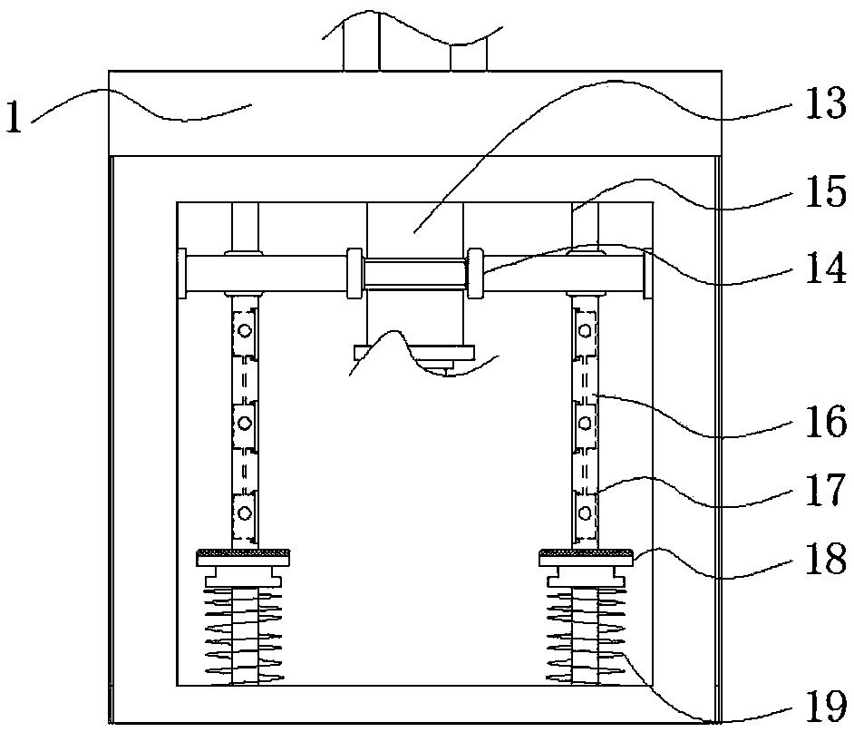
The invention relates to a hydraulic torque converter testing machine provided with a track buffer mechanism and capable of being stably pushed. The testing machine comprises a machine body and a buffer mechanism, a transverse slideway penetrates through the outer wall at the top end of the machine body, and an outer hoisting mechanism is installed outside the transverse slideway, a transmission mechanism is arranged at the middle inside the upper end of the machine body, the outside of the transmission mechanism is connected to a limiting outer stop rod, buffer mechanisms are arranged at theleft end and the right end of the limiting outer stop rod, an equipment chamber is formed in the bottom end of the machine body, and a linkage opening is formed on the inner wall of the equipment chamber in a penetrating mode. The beneficial effects of the invention are that: the hydraulic torque converter testing machine with the track buffer mechanism and capable of being stably pushed is equipped with block inner grooves and inner through grooves, cables can be lapped through inner through grooves in outer line adjusting blocks, the bottom ends of the inner through grooves are a wave-shapedstructure, so that the cables can better fit the inner walls of the inner through grooves, at the same time a plurality of groups of outer cable adjusting blocks are arranged, a plurality of cables can be lapped, and the lapping performance of the cables is enhanced.

Description

technical field [0001] The invention relates to the technical field of testing machines, in particular to a hydraulic torque converter testing machine with a track buffer mechanism that can be pushed smoothly. Background technique [0002] The hydraulic torque converter is a non-rigid torque converter with liquid as the working medium. It is one of the forms of hydraulic transmission. The hydraulic torque converter has a closed working chamber, and the liquid circulates in the chamber. The pump wheel , turbine and guide wheel are respectively connected to the input shaft, output shaft and housing. When the power machine (internal combustion engine, electric motor, etc.) drives the input shaft to rotate, the liquid flows out from the centrifugal pump wheel, passes through the turbine wheel, the guide wheel and then returns to the pump wheel. Circulating flow over and over again, and testing machines are generally used to measure hydraulic torque converters. [0003] The exis...

Claims


Application Information

Patent Timeline
Patent Type & Authority Applications(China)
IPC IPC(8): G01M13/02
CPCG01M13/02
Inventor 吴泓孙卫吴诚源陆雅娟
Owner 上海正源汽车附件有限公司
Why Eureka
Eureka Blog
Learn More