Camera pose calibration method based on spatial point location information

A pose calibration and space point technology, applied in the field of robot vision, can solve problems such as limited precision and cumbersome operation

Active Publication Date: 2020-05-08
EUCLID LABS NANJING CORP LTD
View PDF5 Cites 12 Cited by
  • Summary
  • Abstract
  • Description
  • Claims
  • Application Information

AI Technical Summary

Problems solved by technology

[0004] The invention discloses a camera pose calibration method based on spatial point information, and its purpose is to solve the problem of cumbersome operation and limited accuracy of the existing calibration method for a robot vision system with an independently installed

Method used


Image

  • Camera pose calibration method based on spatial point location information
  • Camera pose calibration method based on spatial point location information
  • Camera pose calibration method based on spatial point location information

Examples


Embodiment Construction

[0059] The present invention will be further described in detail below in combination with example diagrams and specific embodiments.

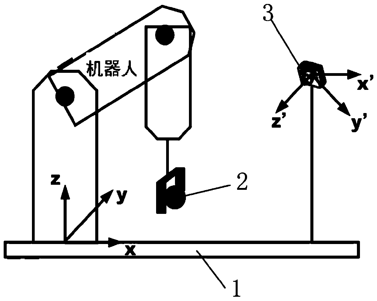
[0060] The present invention provides a camera pose calibration method based on spatial points, based on a robot, a three-dimensional camera acquisition system and a calibration object sphere for program implementation, wherein the robot is a general-purpose six-joint series industrial robot, and the three-dimensional camera has the ability to take pictures in real time and obtain three-dimensional The function of point cloud data, the calibration object sphere adopts table tennis. The table tennis ball is chosen as the calibration object, and its advantage is that the table tennis ball is moderate in size, easy to carry, and the size is an international uniform size, with a diameter of 40mm, and the standard is uniform. The schematic diagram of the construction and scheme of the system equipment is as follows: figure 1 As shown, the specific...


PUM


Abstract

The invention discloses a camera pose calibration method based on spatial point location information. For a robot vision system with an independently-installed camera, a sphere is placed at the tail end of a robot to serve as a calibration object, then the robot is operated to change the position and posture of the sphere to move to different point locations, images and point clouds of table tennis balls at the tail end of the robot are collected; the sphere center is fitted to serve as a spatial point, and meanwhile the corresponding position and posture of the robot are recorded; then a transformation relation between a camera coordinate system and a robot base coordinate system is calculated by searching an equation relation between specific point position changes; the points collectedunder a camera coordinate system are converted into points under a robot base coordinate system, and directly achieving target grabbing of the robot based on visual guidance. According to the invention, the sphere is used as a calibration object, the operation is simple, flexible and portable, the tedious calibration process is simplified, and compared with a method for conversion by means of a calibration plate or a calibration intermediate coordinate system, the method has higher precision, and does not introduce an intermediate transformation relationship and excessive error factors.

Description

technical field [0001] The invention relates to a camera pose calibration method based on spatial point information. Specifically, it uses the position information of multiple sets of points in the robot and the camera coordinate system to solve the pose of the camera relative to the robot and complete the next point in the camera coordinate system. The position conversion to the robot coordinate system belongs to the field of robot vision technology, Background technique [0002] Modern industrial production has higher and higher requirements for repeatability, high precision, and intelligence. Manual operations will inevitably lead to deviations, and a large number of repetitive tasks also cause waste of manpower and resources. In recent years, with the development of intelligent manufacturing technology, robots have been increasingly applied to various fields of production and life. In order to improve the autonomy and intelligence of its operations, machine vision is gr...

Claims


Application Information

Patent Timeline
IPC IPC(8): G06T7/80G06T7/70
CPCG06T7/80G06T7/70G06T2207/30244
Inventor 蒋萌严律王明松王杰高
Owner EUCLID LABS NANJING CORP LTD
Why Eureka
Try Eureka