Array substrate, preparation method thereof and display panel

An array substrate, non-display area technology, applied in semiconductor/solid-state device manufacturing, instruments, semiconductor devices, etc., can solve problems such as large transfer contact impedance, abnormal screen display, and display panel gradient lines

Active Publication Date: 2020-05-08
TCL CHINA STAR OPTOELECTRONICS TECH CO LTD
View PDF18 Cites 7 Cited by
  • Summary
  • Abstract
  • Description
  • Claims
  • Application Information

AI Technical Summary

Problems solved by technology

see figure 1 , which is a schematic structural diagram of a gate drive circuit of an existing display panel. The surface of the first metal layer 101 and the second metal layer 102 are overlapped by a conductive layer 103. Specifically, the conductive layer 103 is connected by a gate insulating layer The via holes on the protective layer 104 and the via holes on the protective layer 105 realize the electrical connection between the first metal layer 101 and the second metal layer 102, between the first metal layer 101 and the second metal layer 102 There will be a large transfer contact resistance, and the conductive layer 103 is prone to corrosion under negative voltage, resulting in poor overlap between the first metal layer 101 and the second metal layer 102, resulting in the appearance of the display panel. Gradient line, screen display abnormal problem

Method used


Image

  • Array substrate, preparation method thereof and display panel
  • Array substrate, preparation method thereof and display panel
  • Array substrate, preparation method thereof and display panel

Examples


Embodiment Construction

[0044] The technical solutions in the embodiments of the present application will be clearly and completely described below in conjunction with the drawings in the embodiments of the present application. Apparently, the described embodiments are only some of the embodiments of this application, not all of them. Based on the embodiments in this application, all other embodiments obtained by those skilled in the art without making creative efforts belong to the scope of protection of this application.

[0045]In the description of the present application, it should be understood that the terms "center", "longitudinal", "transverse", "length", "width", "thickness", "upper", "lower", "front", " Orientation indicated by rear, left, right, vertical, horizontal, top, bottom, inside, outside, clockwise, counterclockwise, etc. The positional relationship is based on the orientation or positional relationship shown in the drawings, which is only for the convenience of describing the ap...


PUM


Abstract

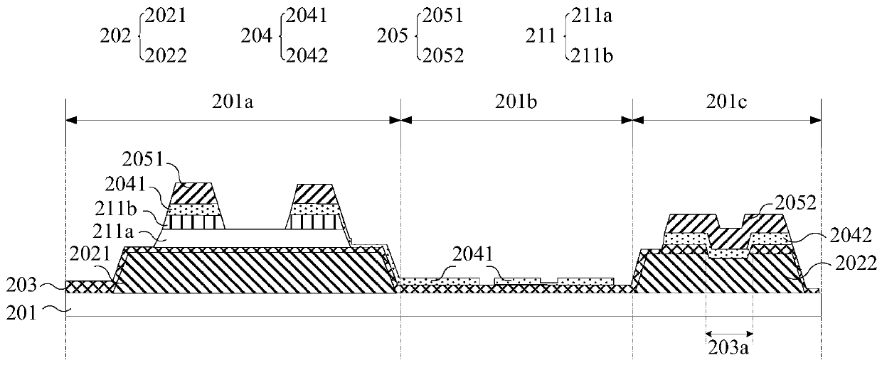
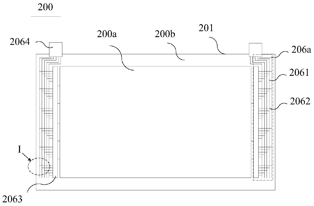
The invention discloses an array substrate, a preparation method and a display panel, and the array substrate comprises: a substrate which is provided with a first region, a second region and a thirdregion; a first metal layer including a first metal member provided in a first region of the substrate and a second metal member provided in a third region of the substrate; a first insulating layer covering the first metal layer and the substrate, wherein a through hole is formed in the position, corresponding to the third area, of the first insulating layer; a conducting layer which comprises afirst conducting part arranged in the first area and the second area and a second conducting part arranged in the third area, wherein at least part of the second conducting part is connected with thesecond metal component through the through hole; and a second metal layer which comprises a third metal component arranged in the first region and a fourth metal component arranged in the third region, wherein the fourth metal component is connected with the second conductive part, so that the contact impedance between the first metal layer and the second metal layer is reduced, the problem that the display panel is easy to generate a gradient line is improved, and the display quality of the display panel is improved.

Description

technical field [0001] The present application relates to the field of display technology, in particular to an array substrate, a manufacturing method thereof, and a display panel. Background technique [0002] In the manufacturing process of the display panel, a total of three exposure masks are required for the second metal layer, the protective layer, and the pixel electrode layer of the array substrate, which are made through three processes of exposure and development. The manufacturing process is complicated and the cost is high. In addition, in order to achieve a narrow frame design, the display panel mostly adopts a structure in which a gate driving circuit (Gate on Array, GOA) is prepared on an array substrate, so the gate driving circuit is formed on the array substrate. see figure 1 , which is a schematic structural diagram of a gate drive circuit of an existing display panel. The first metal layer 101 and the second metal layer 102 are overlapped by a conductive...

Claims


Application Information

Patent Timeline
Patent Type & Authority Applications(China)
IPC IPC(8): H01L27/12H01L21/77G02F1/1333G02F1/1345G02F1/1362
CPCH01L27/124H01L27/1288H01L21/77G02F1/136227G02F1/13452G02F1/1333G02F1/136231G02F1/133388G02F1/133514G02F1/13454G02F1/136286G02F2202/28
Inventor 朱清永
Owner TCL CHINA STAR OPTOELECTRONICS TECH CO LTD
Why Eureka
Try Eureka