Electric slip ring with long service life

A technology of electric slip rings and slip rings, applied in the field of electric slip rings, can solve problems affecting the effective use of electric slip rings, separation of conductive rings and conductive brushes, overheating and deformation of conductive brushes, etc., to ensure long-term effective use and stable contact state, the effect of evenly distributed current

Active Publication Date: 2020-05-08
福建华开电力科技有限公司
View PDF5 Cites 2 Cited by
  • Summary
  • Abstract
  • Description
  • Claims
  • Application Information

AI Technical Summary

Problems solved by technology

[0003] When the existing electric slip ring is in use, abrasive particles will be generated during the contact process between the conductive ring and the conductive brush. After a long time, the abrasive particles will adhere to the contact surface between the conductive ring and the conductive brush to form a bulge, which will easily cause the conductive ring to be damaged. It is separated from the contact surface of the conductive brush, which makes the current distribution of the conductive brush uneven, which affects the effective use of the electric slip ring, and the existing conductive brush relies on its own elasticity to maintain contact with the conductive ring, and the frictional heat of the relative rotation of the conductive ring and the conductive brush and Resistance heat can easily cause the conductive brush to overheat and deform, and weaken the elasticity, which further affects the long-term effective use of the electric slip ring

Method used


Image

  • Electric slip ring with long service life
  • Electric slip ring with long service life
  • Electric slip ring with long service life

Examples


Embodiment Construction

[0016] The technical solutions in the embodiments of the present invention will be clearly and completely described below in conjunction with the accompanying drawings in the embodiments of the present invention. Obviously, the described embodiments are only a part of the embodiments of the present invention, rather than all the embodiments. Based on the embodiments of the present invention, all other embodiments obtained by those of ordinary skill in the art without creative work shall fall within the protection scope of the present invention.

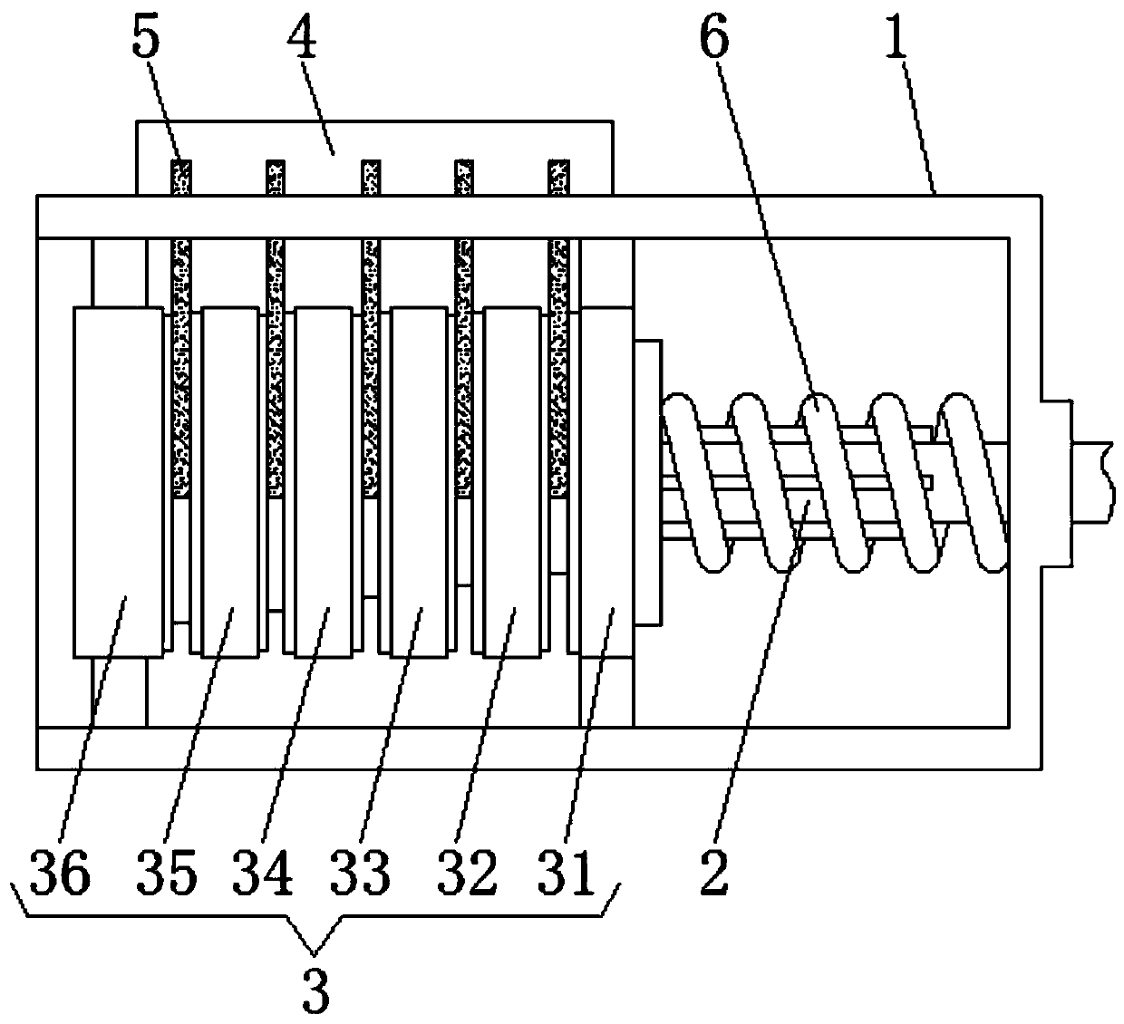
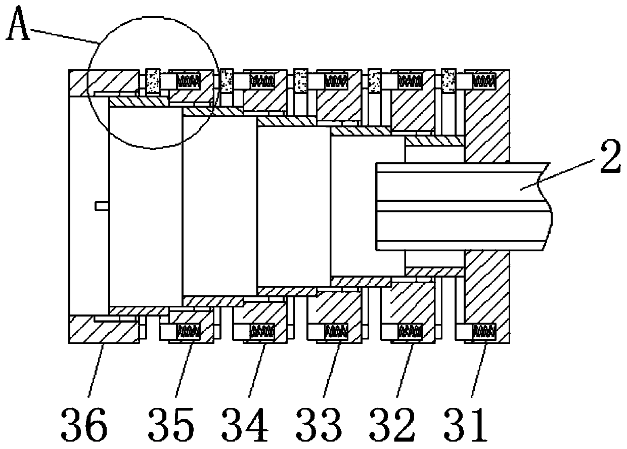
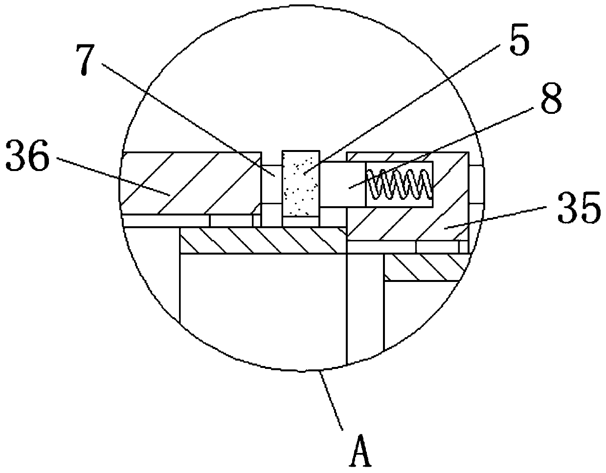
[0017] See Figure 1-3 , An electric slip ring with high service life, comprising a protective shell 1, one side of the protective shell 1 is slidingly sleeved with a transmission shaft 2, and one end of the transmission shaft 2 is slidingly sleeved with a slip ring assembly 3 inside the protective shell 1, The slip ring assembly 3 rotates with the drive shaft 2, and the slip ring assembly 3 can slide on the drive shaft 2. The top of the...


PUM


Abstract

The invention relates to the field of power equipment devices and discloses an electric slip ring with a long service life. A protection shell is included, a transmission shaft is connected to one side in a sliding manner, a sliding ring assembly located in the protection shell is slidably provided with one end of the transmission shaft, the sliding ring assembly rotates along with the transmission shaft and can slide on the transmission shaft, a wiring terminal is arranged at a top of the protection shell, and conductive brushes making contact with the sliding ring assembly are arranged on afront surface and a back surface of the wiring terminal. By using the electric slip ring with the long service life, each group of slip rings is movably connected with each other, conductive rings incontact with the conductive brushes are arranged on the side surfaces of each group of slip rings, and an elastic action of a compensation spring can be utilized so that each conductive brush and theconductive ring can be kept in a stable contact state, a mode that an elastic force of the conductive brush keeps contact is canceled, phenomena that the conductive brush is deformed due to overheating and cannot be in stable contact with the conductive ring are effectively avoided, and long-term stable use of the electric slip ring is ensured.

Description

Technical field [0001] The invention relates to the field of power equipment devices, in particular to an electric slip ring with a long service life. Background technique [0002] Electric slip ring, also known as slip ring, or rotary joint, rotating electrical interface, slip ring, current collecting ring, return ring, coil, commutator, adapter, is the image and data signal that realizes two relative rotation mechanisms And the precision power transmission device for power transmission is widely suitable for unrestricted continuous rotation, and at the same time, it is necessary to transmit power or data from a fixed position to a rotating position. [0003] When the existing electric slip ring is in use, abrasive particles will be generated during the contact between the conductive ring and the conductive brush. After a long time, the abrasive particles will adhere to the contact surface between the conductive ring and the conductive brush to form protrusions, which will easily ...

Claims


Application Information

Patent Timeline
Patent Type & Authority Applications(China)
IPC IPC(8): H01R39/08H01R39/18H01R39/36
CPCH01R39/08H01R39/18H01R39/36
Inventor 包平
Owner 福建华开电力科技有限公司
Why Eureka
Try Eureka