
Double-input high-step-up-ratio direct-current converter with pump-up capacitor

A technology of DC converter and high step-up ratio, which is applied in the direction of converting DC power input to DC power output without intermediate conversion to AC conversion equipment, adjusting electrical variables, etc., and can solve discontinuous, complex system structure, and environment-dependent Condition changes and other issues, to achieve the effect of increasing voltage gain, high conversion efficiency, and high boost ratio

Inactive Publication Date: 2020-05-08
FUZHOU UNIV
View PDF8 Cites 0 Cited by
  • Summary
  • Abstract
  • Description
  • Claims
  • Application Information

AI Technical Summary

Problems solved by technology

[0003] Due to the shortcomings of new energy power generation systems such as photovoltaic cells, such as unstable power supply, discontinuity, and changes with environmental conditions, it is impossible to ensure that the load can obtain sufficient energy
Therefore, the independent work of a certain new energy cannot fully meet the user's requirements for stable power supply, so people put forward the concept of multiple new energy joint power supply
Since the DC output voltage level of a single photovoltaic cell is low, it cannot meet the voltage level requirements of the grid-connected inverter DC side, so it is necessary to add a high boost ratio DC converter at the front end of the DC bus side of the power generation system to increase the voltage level. Ensuring that the power generation system injects the generated electricity into the grid
[0004] In the traditional new energy combined power generation system, each input source needs a single-input high-boost ratio DC converter to regulate its voltage. The system structure is complex, the cost is high, and it has its own randomness, intermittent, Limitations such as regionality and output nonlinearity have greatly restricted the development of new energy combined power generation technology

Method used


Image

  • Double-input high-step-up-ratio direct-current converter with pump-up capacitor
  • Double-input high-step-up-ratio direct-current converter with pump-up capacitor
  • Double-input high-step-up-ratio direct-current converter with pump-up capacitor

Examples


Embodiment Construction

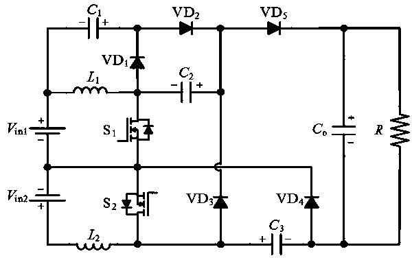
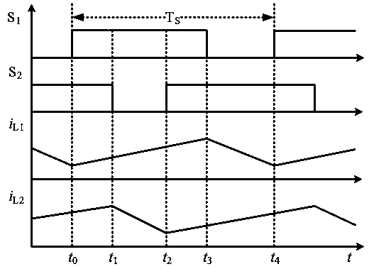
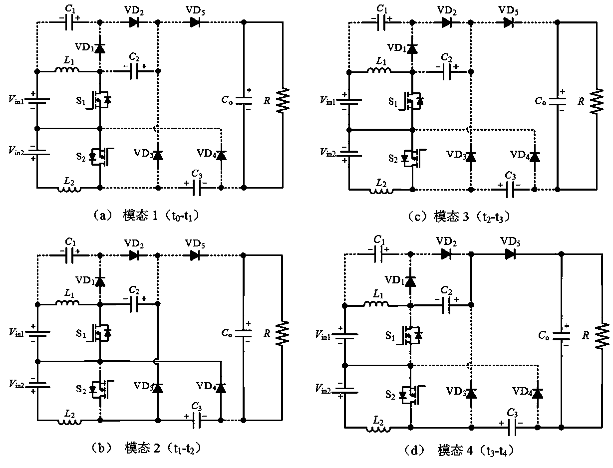
[0028] Attached below Figure 1-12 , the technical solution of the present invention is described in detail.

[0029] The present invention provides a dual-input high boost ratio DC converter with a pumping capacitor, comprising a first input port, a second input port, a first switch tube, a second switch tube, a first diode, a second switch tube, and a first switch tube. Second diode, third diode, fourth diode, fifth diode, first inductance, second inductance, first capacitor, second capacitor, third capacitor, fourth capacitor and load; The positive input end of an input port is connected to the first inductor and one end of the first capacitor, the other end of the first inductor is connected to the anode of the first diode, one end of the second capacitor, and the drain of the first switch tube. The other end of a capacitor is connected to the cathode of the first diode and the anode of the second diode, and the other end of the second capacitor is connected to the cathod...


PUM


Abstract

The invention relates to a double-input high-step-up-ratio direct-current converter with a pump-up capacitor. The converter comprises a first input port, a second input port, a first switch tube, a second switch tube, a first diode, a second diode, a third diode, a fourth diode, a fifth diode, a first inductor, a second inductor, a first capacitor, a second capacitor, a third capacitor, a fourth capacitor and a load. According to the double-input high-step-up-ratio direct-current converter, a voltage gain is improved through the pump-up capacitor, functions of two single-input single-output high-step-up-ratio converters can be achieved in one converter, and two paths of power can be supplied at the same time. The converter has advantages of a high step-up ratio, high conversion efficiency,high reliability and the like, and is very suitable for double-input high-step-up-ratio direct-current voltage conversion occasions.

Description

technical field [0001] The invention relates to the technical field of power electronics, in particular to a double-input high-boost ratio DC converter with a pump-up capacitor. Background technique [0002] Energy is the material basis and source of power for the development and progress of the entire human society. With the depletion of traditional fossil energy and the increasingly serious problems of environmental pollution and global warming caused by it, the development and utilization of new energy has become more and more popular. people's attention. At present, the most widely used new energy power generation methods mainly include photovoltaic power generation, wind power generation, fuel cell power generation, etc., which have the characteristics of wide distribution of resources, great development potential, small environmental impact, and sustainable utilization, and have become the focus of attention and research by countries around the world. hotspot. [000...

Claims


Application Information

Patent Timeline
Patent Type & Authority Applications(China)
IPC IPC(8): H02M3/155H02M3/07
CPCH02M3/07H02M3/155
Inventor 林国庆林思圻
Owner FUZHOU UNIV
Learn More