
Switching power supply device

A technology of switching power supply and main switch, which is applied in the direction of output power conversion device, electrical components, and adjustment of electric variables, etc. It can solve the problems of reducing the effective value of current, adverse effects of converter efficiency, and unfavorable converter efficiency, etc., and achieves the reduction of current Effective value, improvement of light load efficiency, effect of improving light load efficiency

Active Publication Date: 2020-05-08
MORNSUN GUANGZHOU SCI & TECH
View PDF11 Cites 13 Cited by
  • Summary
  • Abstract
  • Description
  • Claims
  • Application Information

AI Technical Summary

Problems solved by technology

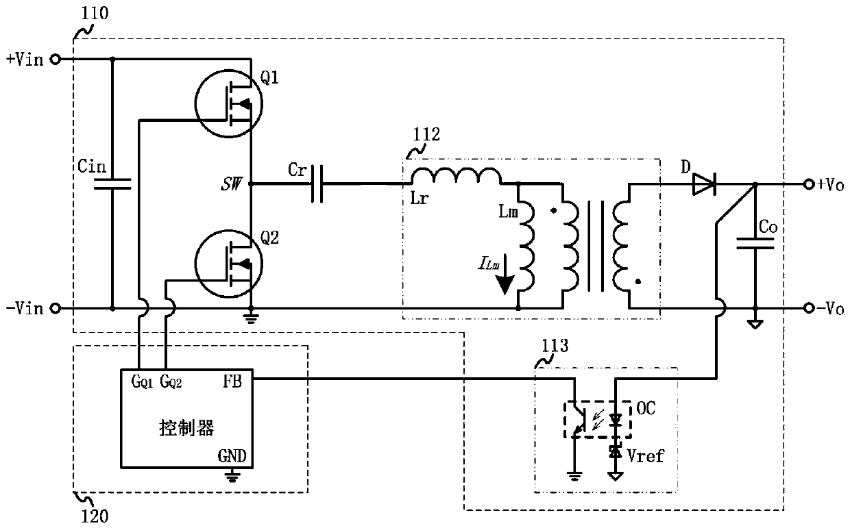
While retaining the existing technical solution to achieve zero-voltage turn-on, this solution can effectively control the negative peak value of the excitation inductor current, reduce the effective value of the current of the power device under light load of the converter, and improve the efficiency of the converter at light load. Reduce the no-load loss, but the intervention of the unidirectional clamping network is unfavorable to the efficiency of the converter under full load and heavy load. This can be clearly seen from the attached drawing 11-1 of the patent. The efficiency of the patented solution in the range of -5A is slightly lower than that of the existing technical solution, that is, the patented solution is beneficial to reduce the light load and no-load loss of the converter, but it will be detrimental to the efficiency of the heavier load converter influences

Method used


Image

  • Switching power supply device
  • Switching power supply device
  • Switching power supply device

Examples


Embodiment Construction

[0033] In order to make the present invention clearer, the prior art solutions and the technical solutions of the present invention will be described more clearly and completely below in conjunction with the drawings and specific embodiments.

[0034] The terms involved in the specific implementation are defined below:

[0035] The anode of the one-way clamping network: the end where the DC current flows inward from the one-way clamping network is the anode;

[0036] The cathode of the one-way clamping network: the end where the DC current flows out from the one-way clamping network is the cathode;

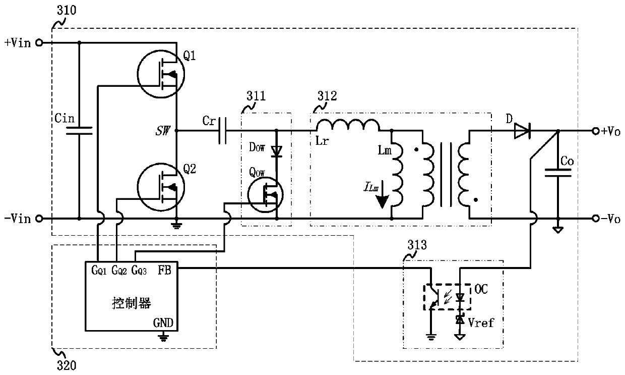
[0037] Clamping current: the current flowing through the one-way clamping network, specifically, in the demagnetization stage, when the exciting inductor current reaches the set value, the auxiliary switch is controlled to be turned off, and the exciting inductor current flowing through the one-way clamping network or passing through The current coupled by the transformer to the ...


PUM


Abstract

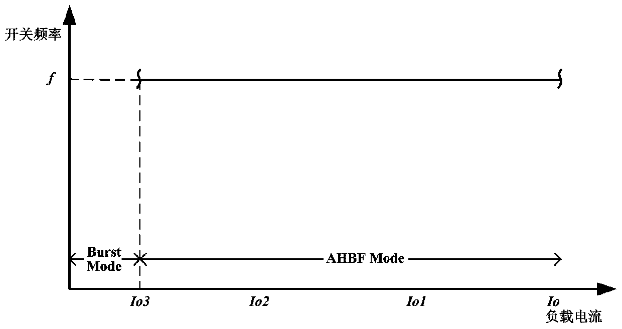
The invention discloses a switching power supply device. The switching power supply device comprises an asymmetric half-bridge flyback converter and a controller; and the asymmetric half-bridge flyback converter is used for converting an input voltage into an output voltage, and comprises a main switch, an auxiliary switch, a transformer and a one-way clamping network used for controlling a negative peak value of an excitation inductive current. A controller is used for controlling the main switch, the auxiliary switch and the one-way clamping network, so that the switching power supply deviceworks in a certain working state. The switching power supply device is characterized in that when the output load current is greater than or equal to a first load current set value, the controller enables the switching power supply device to work in an asymmetric half-bridge flyback mode; and when the output load current is smaller than the first load current set value, the controller enables theswitching power supply device to work in a clamping asymmetric half-bridge flyback mode. Under the condition that the advantages of full load and heavy load high efficiency of the switching power supply device are kept, the current effective value of the power device under light load and no load can be reduced, the light load efficiency is greatly improved, and the no-load loss is reduced.

Description

technical field [0001] The invention relates to a switching power supply device, in particular to a switching power supply device composed of an asymmetrical half-bridge converter. Background technique [0002] Switching power supply has advantages unmatched by other power supplies, and is widely used in various industries such as industrial production, transportation, medical treatment, communication and consumer electronics. With the development of the electronics industry, more and more electronic products appear in our daily life. Government agencies and industry organizations around the world have formulated corresponding energy consumption standards to help better control the standby function of products. Consumption and conversion efficiency, cost savings to protect the environment and upgrade the market level. Relevant energy efficiency standards have also been formulated for switching power supplies in the world, which not only require the power supply to have high...

Claims


Application Information

Patent Timeline
IPC IPC(8): H02M3/335
CPCH02M3/33569H02M1/0048Y02B70/10
Inventor 任鹏程江波张法旺
Owner MORNSUN GUANGZHOU SCI & TECH
Learn More