Efficient laminating machine applied to prefabricated slab

A technology of laminating machine and prefabricated board, applied in the direction of manufacturing tools, ceramic molding machines, etc., can solve the problems of high production cost, unsuitable for prefabricated board, bulky and other problems, and achieve good maintenance work, good attachment effect and processing efficiency high effect

Active Publication Date: 2020-05-12
佛山市晋翊新材料有限公司
View PDF10 Cites 3 Cited by
  • Summary
  • Abstract
  • Description
  • Claims
  • Application Information

AI Technical Summary

Problems solved by technology

[0005] The purpose of the present invention is to address the deficiencies of the prior art. By setting up a lifting mechanism and a film covering mechanism to complete the automatic film covering of the prefabricated plate, and after covering the film, it can be automatically cut by the film cutting mechanism, and then cooperate with the film pressing mechanism. , can automatically press the coated film to make the film stick tightly, thus solving the technical problem that the film coating die-cutting machine has a large volume, high production cost, and is not suitable for application in the coating and maintenance of prefabricated panels

Method used


Image

  • Efficient laminating machine applied to prefabricated slab
  • Efficient laminating machine applied to prefabricated slab
  • Efficient laminating machine applied to prefabricated slab

Examples


Embodiment 1

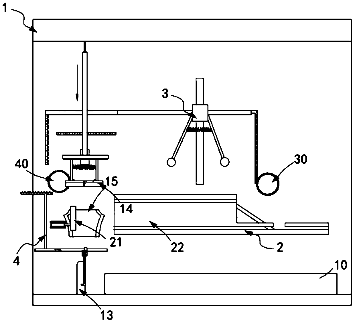
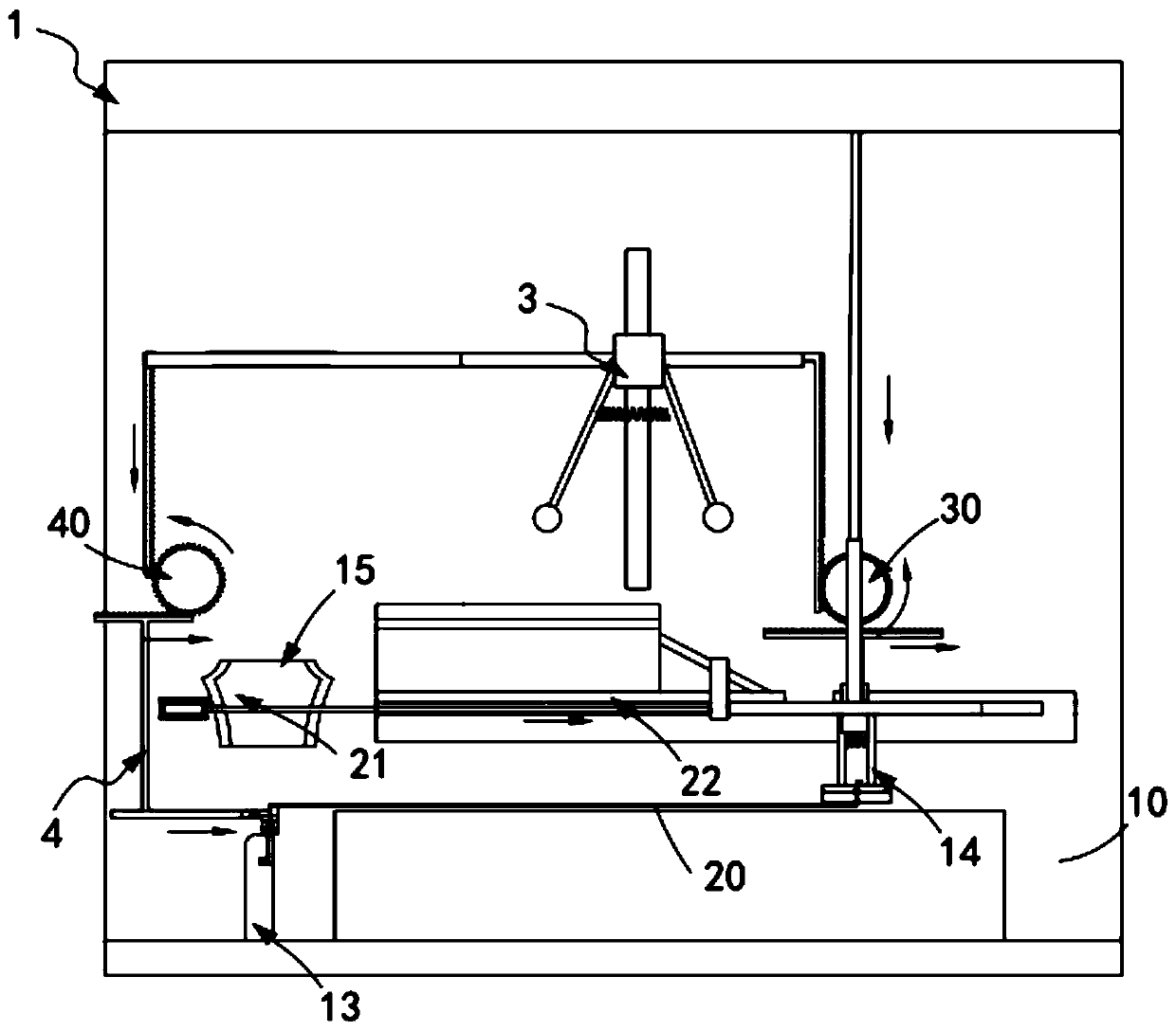
[0079] Such as figure 1 , figure 2 As shown, a high-efficiency laminating machine applied to prefabricated panels, including:

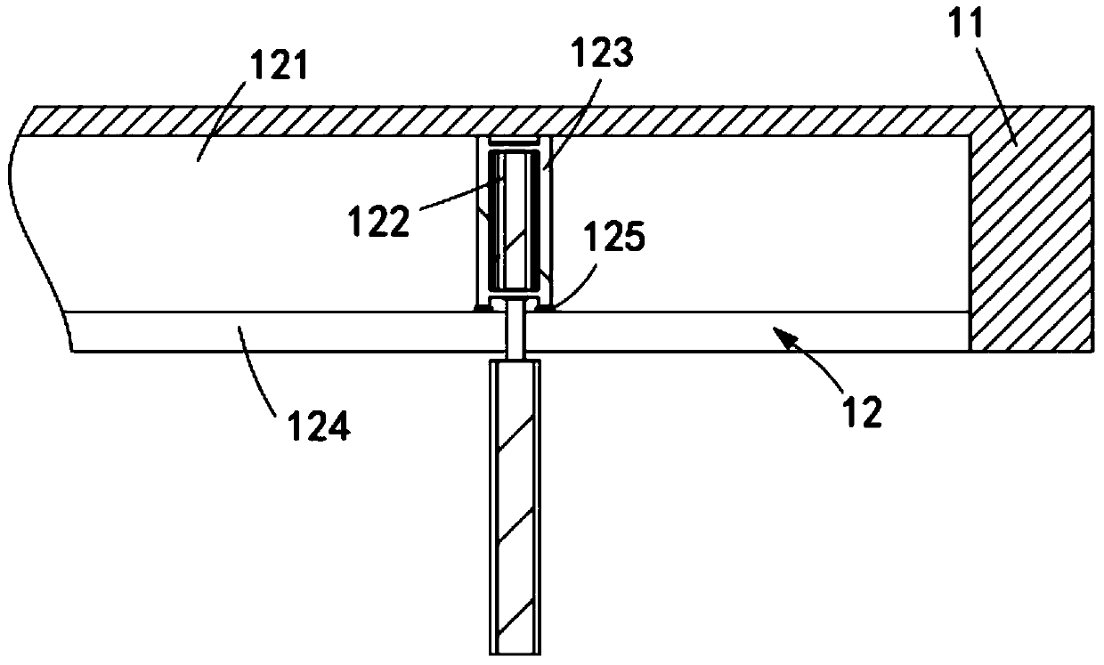
[0080] Lifting mechanism 1, described lifting mechanism 1 comprises frame 11, is installed on the top of described frame 11 and horizontally reciprocatingly slides on described frame 11 the first air pushing assembly 12, is installed under described frame 11 The film release part 13, the clamping assembly 14 fixedly connected to the telescopic end of the first air pushing assembly 12 above the film release part 13, and the clamping assembly 14 installed on the frame 11 and located at the clamping assembly 14 A guide assembly 15 provided on one side, the guide assembly 15 is used to guide the opening and closing of the clamping assembly 14;

[0081] The film covering mechanism 2, the film covering mechanism 2 includes a second air pushing assembly 21 installed on the frame 11 and arranged horizontally and a sliding assembly 22 arranged along the hor...

Embodiment 2

[0133] Such as Figure 9 , Figure 11 As shown, the components that are the same as or corresponding to those in the first embodiment are marked with the corresponding reference numerals in the first embodiment. For the sake of simplicity, only the differences from the first embodiment will be described below. The difference between this embodiment two and embodiment one is:

[0134] further, such as Figure 8 As shown, the laminating mechanism 3 includes:

[0135] Lifting plate 31, the lifting plate 31 slides up and down on the frame 11;

[0136] A support block 32, the support block 32 is fixedly arranged at the central position of the lifting plate 31;

[0137] Pressing roller unit 33, said pressing roller unit 33 is provided with two groups and arranged symmetrically along the midline on the length of said support block 32, which includes a swing plate 331 rotatably arranged on said support block 32 and fixedly arranged on said support block 32. the pressure roller a3...


PUM


Abstract

The invention relates to an efficient laminating machine applied to a prefabricated slab. The efficient laminating machine comprises a lifting mechanism, a laminating mechanism, a film pressing mechanism and a film cutting mechanism, wherein the lifting mechanism comprises a rack, a first air-pushing assembly, a film releasing part, a clamping assembly and a guiding assembly, and the guiding assembly is used for guiding the clamping assembly to open and close; the laminating mechanism comprises a second air-pushing assembly which is mounted on the rack and is horizontally arranged and a sliding assembly arranged in a horizontal pushing direction of the second air-pushing assembly, and the first air-pushing assembly is arranged vertical to the telescopic direction of the second air-pushingassembly; the film pressing mechanism is slidably arranged on the rack in the vertical direction through a first transmission assembly; and the film cutting mechanism is driven synchronously with thefilm pressing mechanism through a second transmission assembly and cuts a film during transmission. The efficient laminating machine solves the technical problem that existing laminating die cutting machine equipment which is large in size and high in manufacturing cost is not suitable for being applied to coating and preserving the prefabricated slab.

Description

technical field [0001] The invention relates to the technical field of film covering, in particular to a high-efficiency film covering machine applied to prefabricated panels. Background technique [0002] When making prefabricated panels, first use wooden boards to nail the hollow model, after distributing steel bars in the hollow part of the model, fill the hollow part with cement, knock off the wooden board after it dries, and the rest is the prefabricated board. At present, when the prefabricated panels are processed, the coating needs to be maintained. However, since the prefabricated panels are currently covered with artificial pulling films, they are manually leveled after covering. It is better to be attached to the board, otherwise the air between the film and the board will easily affect the forming effect of the board. [0003] The patent document with the patent number CN2013200877368 discloses a single-layer material laminating die-cutting machine, which sequen...

Claims


Application Information

Patent Timeline
Patent Type & Authority Applications(China)
IPC IPC(8): B28B11/24
CPCB28B11/245
Inventor 钱丽峰
Owner 佛山市晋翊新材料有限公司
Why Eureka
Try Eureka