Electrode cap replacement machine

An electrode cap and replacement machine technology, applied in resistance welding equipment, auxiliary devices, auxiliary welding equipment and other directions, can solve the problems of cumbersome and time-consuming disassembly process, complex structure, inconvenient control, etc., to achieve compact structure, reasonable structure layout, and convenient control. Effect

Pending Publication Date: 2020-05-15
GUANGZHOU KYOKUTOH CHINA
View PDF11 Cites 2 Cited by
  • Summary
  • Abstract
  • Description
  • Claims
  • Application Information

AI Technical Summary

Problems solved by technology

The existing knob-type electrode cap replacement machine can basically only disassemble the electrode cap with the knob in one direction, so when disassembling the electrode caps on the upper and lower electrode rods, the disassembly process using the existing electrode cap replacement machine is relatively cumbersome Time-consuming, although some electrode cap replacement machines can achieve two-way cap removal, but the structure is more complicated and inconvenient to operate

Method used


Image

  • Electrode cap replacement machine
  • Electrode cap replacement machine
  • Electrode cap replacement machine

Examples


Embodiment 1

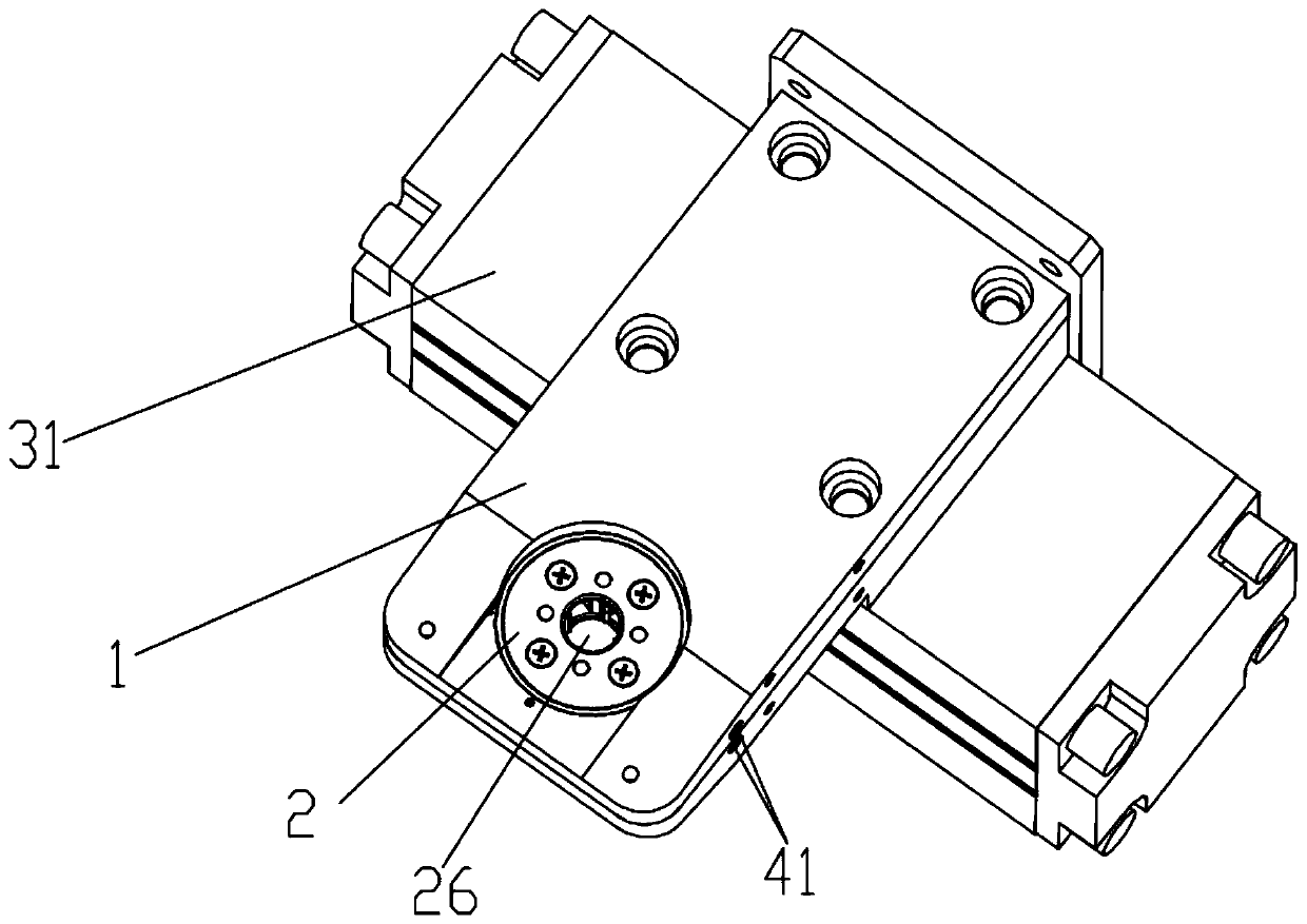
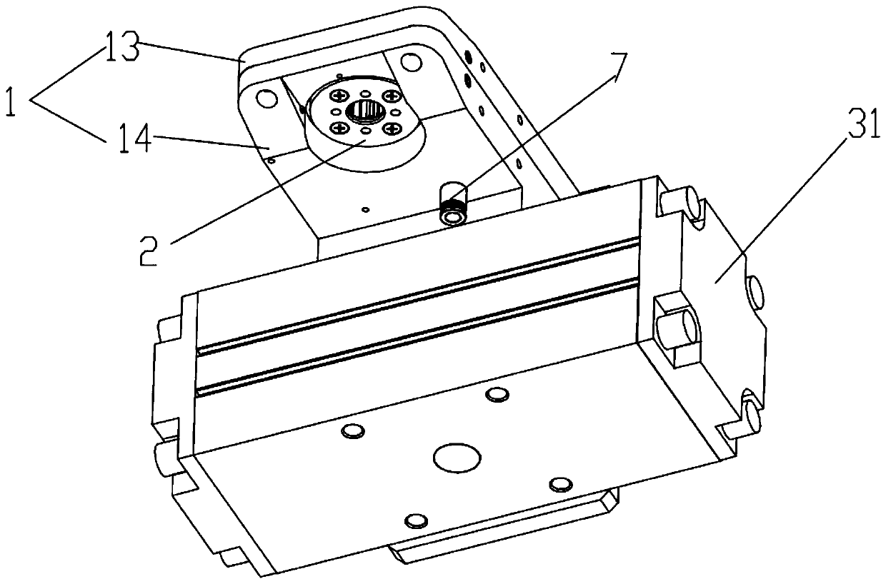
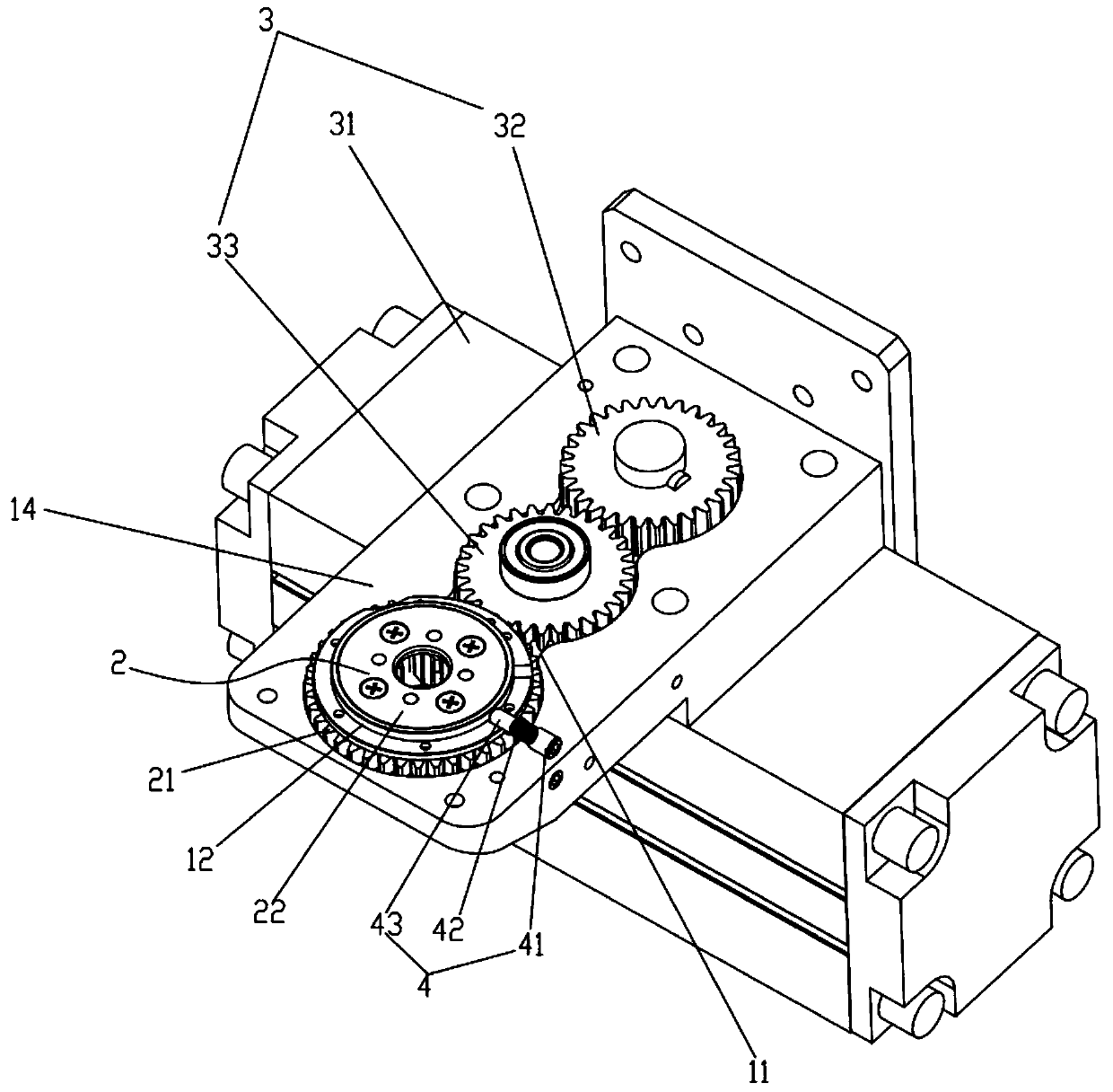
[0030] Such as Figure 1-6 As shown, the electrode cap replacement machine includes a housing 1, a cap removal head 2, a driving device 3 and a damper 4. The housing 1 is provided with an accommodation chamber 11, and the cap removal head 2 is movable in the accommodation chamber 11. Head 2 comprises decapping gear 21, claw cover 22 and four claws 23, and claw cover 22 comprises upper cover 221 and lower cover 222, and upper cover 221 and lower cover 222 are positioned at the both sides of decapping gear 21 respectively and pass Four connecting pins 24 are fixedly connected together, the cap removal gear 21 is located between the upper cover 221 and the lower cover 222 and can rotate relative to the claw cover 22, the cap removal gear 21 is a hollow ring structure, and the four claws 23 are along the The circumferential direction is evenly placed in the inner ring of the cap removal gear 21, and the rear ends of each claw 23 are respectively hinged with the inner wall of the c...

Embodiment 2

[0042] On the basis of embodiment 1 technical scheme, make following improvement:

[0043] Such as Figure 7 As shown, an electrode cap detector 5, an upper electrode cap feeder 61 and a lower electrode cap feeder 62 are added to the housing 1 of the electrode cap replacement machine, wherein the upper electrode cap feeder 61 and the lower electrode cap feeder 62 are respectively It is installed on the left and right sides of the housing 1, and is arranged side by side with the cap removal head 2 horizontally. Among them, the upper electrode cap feeder 61, the lower electrode cap feeder 62, and the electrode cap detector 5 can adopt the applicant’s prior application and disclosed technology, or can use the existing technology in this field, and its detailed structure will not be discussed herein. repeat.

[0044] Compared with the prior art, the electrode cap replacement machine of the present invention has the following advantages: ① A longitudinal clamping blade 231 is arr...


PUM


Abstract

The invention relates to the technical field of welding, in particular to an electrode cap replacement machine. The electrode cap replacement machine comprises a casing, a cap dismounting head, a driving device and a damper, wherein the cap dismounting head is movably arranged in the casing and comprises a cap dismounting gear, a clamping jaw cover and a plurality of clamping jaws, the cap dismounting gear can rotate relative to the clamping jaw cover, the clamping jaws are uniformly arranged on an inner ring of the cap dismounting gear, the rear ends of the clamping jaws are hinged with the inner wall of the cap dismounting cap, longitudinal clamping blades are arranged at the front end of the clamping jaws, the clamping jaws are hinged with the clamping jaw cover, the damper is mounted on the casing and can perform damping positioning on the clamping jaw cover, and the driving device can drive the cap dismounting gear to rotate. The electrode cap replacement machine can realize forward and reverse cap dismounting by means of the clamping blades of a double-blade structure and is simple in structure and convenient to operate.

Description

technical field [0001] The invention relates to the field of welding technology, in particular to an electrode cap replacement machine. Background technique [0002] At present, the welding torch and the electrode rod are generally connected by threads, and the electrode cap and the electrode rod are generally tightly fitted by a conical surface. This requires that when removing the electrode cap, in order to prevent the electrode rod from being removed or loosened together, the best action to remove the cap is Based on the principle of "knob" cap removal, remove the electrode cap along the direction of the electrode rod thread rotation, that is, go to the knob to remove the electrode cap along the direction of the electrode rod thread tightening, so, for the electrode caps on the upper and lower electrode rods In other words, the removal direction is the opposite. The existing knob-type electrode cap replacement machine can basically only disassemble the electrode cap with...

Claims


Application Information

Patent Timeline
Patent Type & Authority Applications(China)
IPC IPC(8): B23K11/36B23K37/00
CPCB23K11/36B23K37/00
Inventor 刘军良杨贤德
Owner GUANGZHOU KYOKUTOH CHINA
Why Eureka
Try Eureka