Steel pipe end sealing device and using method

A steel pipe and end-sealing technology, which is applied in packaging, metal material coating technology, etc., can solve the problems of high firmness socket efficiency, end-sealing sleeve drop, and low firmness socket efficiency, etc.

Pending Publication Date: 2020-05-15
ZHANGJIAGANG CITY SHENGDINGYUAN PIPE MAKING
View PDF0 Cites 4 Cited by
  • Summary
  • Abstract
  • Description
  • Claims
  • Application Information

AI Technical Summary

Problems solved by technology

[0003] The purpose of the present invention is to provide a steel pipe end sealing device, which is used to solve the problem in the prior art that the manual sealing of the end sleeve of the steel pipe port cannot maintain high firmness, the socket efficiency is slow, and the end sealing sleeve is likely to fall off.
[0005] In the above technical solution, in order to solve the problem that the manual sealing of the steel pipe port can not maintain a high degree of firmness, the embodiment of the present application adopts a conveying device, a fixed device, pushing device, put the steel pipe to be sealed into the arc groove of the clamping wheel through the clamping wheel of the conveying device, and then move the steel tube to the fixing device through the sliding base connected with the clamping wheel Below, the telescopic motor of the fixing device drives the fixed base to move downward, so that the fixed base and the sliding base fit together to fix the clamping wheel, and then the pushing cylinder of the pushing device starts to drive the The end cap moves to the clamping wheel, so that the end cap is buckled into the port of the steel pipe, and multiple steel pipes are collected by the clamping wheel, so that when the end cap is buckled by the pushing device, multiple steel pipes can be collected. The steel pipe is sealed to improve the sealing efficiency. At the same time, the sealing cover and the steel pipe port of the push cylinder have high fastness, and the steel pipe after sealing has high firmness.

Method used


Image

  • Steel pipe end sealing device and using method
  • Steel pipe end sealing device and using method
  • Steel pipe end sealing device and using method

Examples


Embodiment 1

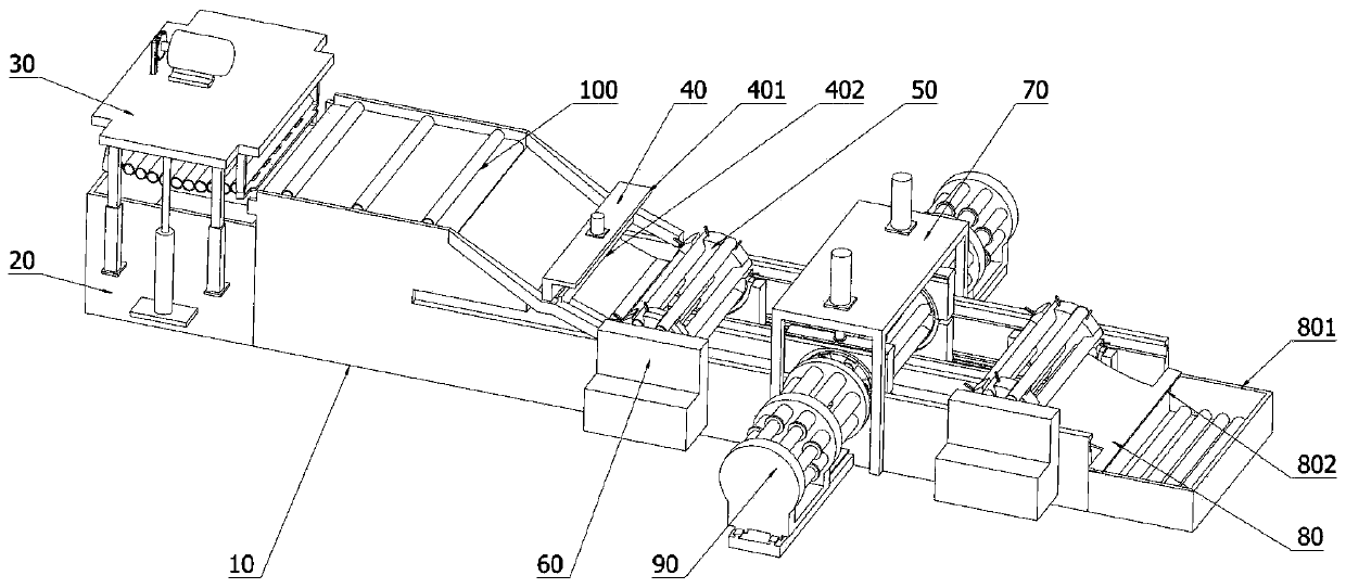
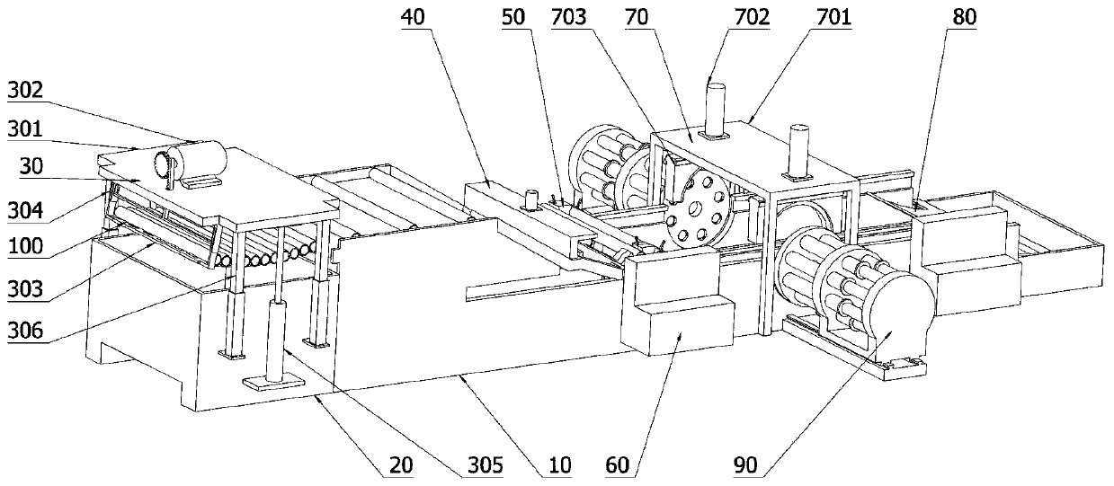
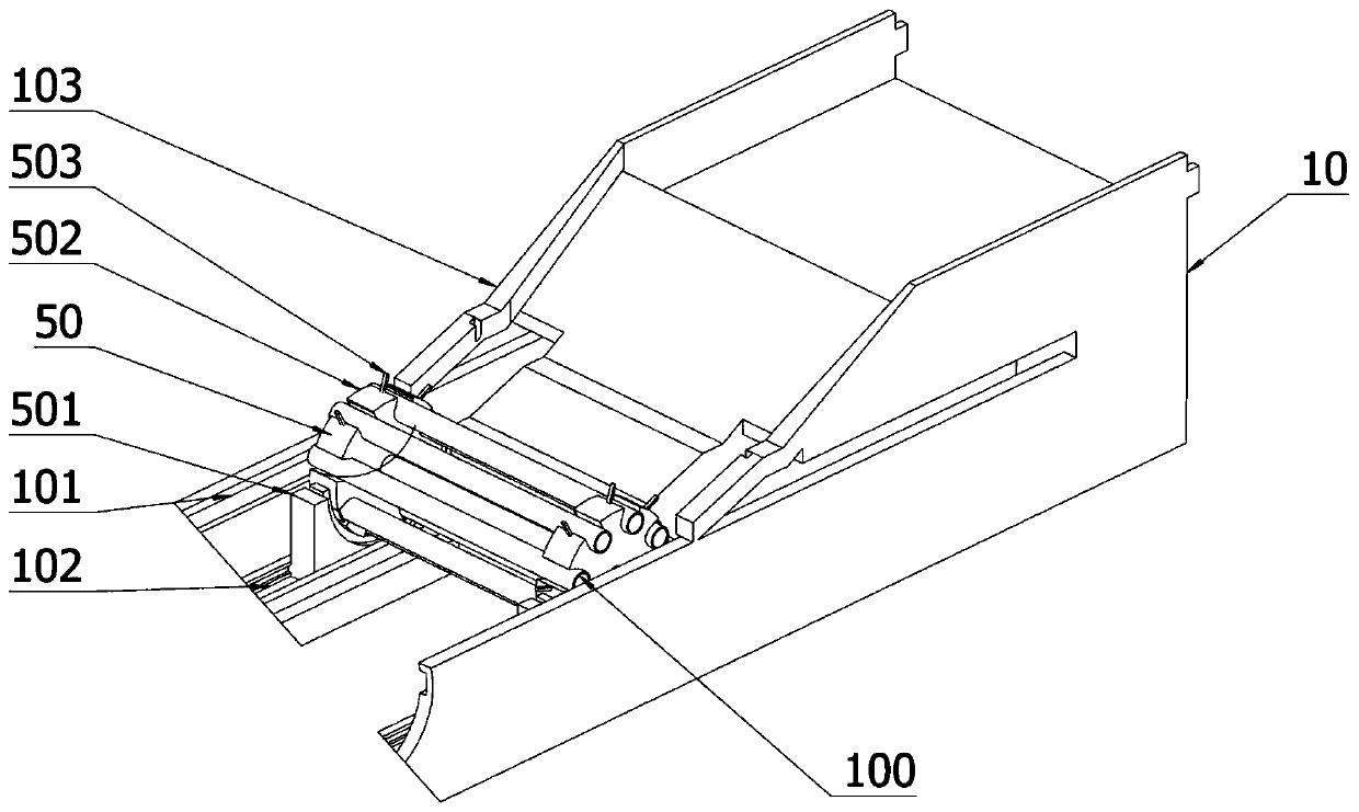
[0058] Such as figure 1 , 3 As shown in . , fixed base 703, pushing device 90, butt joint 904, end cap 906, pushing cylinder 905, frame 10 is arranged on the plane; conveying device 50 is arranged on the inside of frame 10, and conveying device 50 is not connected with machine The inner wall surface of frame 10 contacts, and delivery device 50 comprises: sliding base 501 is arranged on the inside of frame 10, and sliding base 501 is connected with frame 10, and sliding base 501 has semicircular arc-shaped surface; The connecting wheel 502 is arranged inside the frame 10, the locking wheel 502 is not in contact with the inner wall of the frame 10, the locking wheel 502 is arranged on the arc surface of the sliding base 501, and the locking wheel 502 is in contact with the inner wall surface of the frame 10. The arc-shaped surface of the sliding base 501 forms the same circle center, and the surface of the clamping wheel 502 is provided with an arc-shaped groove, and the arc-s...


PUM


Abstract

The invention discloses a steel pipe end sealing device, and relates to the technical field of machining. The steel pipe end sealing device comprises a rack arranged on a plane and a conveying devicearranged inside the rack, wherein the conveying device comprises a sliding base arranged inside the rack, a clamping wheel plate arranged inside the rack and a fixing device arranged above the rack, the fixing device comprises a placing frame arranged above the rack, telescopic motors arranged on the placing frame, a fixing base arranged inside the placing frame, a semicircular arc-shaped surfaceis formed in the fixing base and a pushing and pressing device arranged on one side of the rack and fixedly connected with the rack, and the pushing and pressing device comprises a butt joint pipe arranged on the outer side of the rack, an end sealing cover arranged inside the butt joint pipe and a pushing and pressing air cylinder arranged on one side of the butt joint pipe. According to the steel pipe end sealing device and the using method, the problems that high firmness cannot be kept and the sleeving efficiency is low when an end sealing sleeve manually sleeves an end port of a steel pipe, and the end sealing sleeve is easily caused to fall off are prevented.

Description

technical field [0001] The invention relates to the technical field of mechanical processing, in particular to a steel pipe end sealing device. Background technique [0002] As an important material in construction, steel pipes are widely used in engineering construction. As we all know, steel pipes are exposed to humid air for a long time, and the surface of steel pipes will rust due to moisture. At the same time, the inner wall of steel pipes is also prone to rust spots. The rust spots on the inner wall of the steel pipe are relatively easy to remove, but the rust spots on the inner wall of the steel pipe are not easy to remove, and the removal work is cumbersome. Therefore, the outer wall of the port on both sides of the steel pipe is usually sleeved with a sealing sleeve to reduce the intrusion of foreign matter during handling, transportation, and storage. The inner wall of the steel pipe causes corrosion of the inner wall of the steel pipe. However, manual socketing is...

Claims


Application Information

Patent Timeline
Patent Type & Authority Applications(China)
IPC IPC(8): B65B61/20B65B35/10C23C22/00
CPCB65B35/10B65B61/20C23C22/00
Inventor 陈俞银
Owner ZHANGJIAGANG CITY SHENGDINGYUAN PIPE MAKING
Why Eureka
Try Eureka