Clutch pressure determination method and device, vehicle and storage medium

A clutch pressure and determination method technology, applied to clutches, fluid-driven clutches, non-mechanical drive clutches, etc., can solve problems that affect vehicle driving safety, driving stability, impact or flameout, and cost increase

Active Publication Date: 2020-05-15
CHINA FIRST AUTOMOBILE
View PDF6 Cites 2 Cited by
  • Summary
  • Abstract
  • Description
  • Claims
  • Application Information

AI Technical Summary

Problems solved by technology

[0004] However, the use of dual redundant sensors for oil circuit pressure collection increases the cost of vehicle formation, and redundant sensors are doing useless work most of the time, which affects the efficiency of veh

Method used


Image

  • Clutch pressure determination method and device, vehicle and storage medium
  • Clutch pressure determination method and device, vehicle and storage medium
  • Clutch pressure determination method and device, vehicle and storage medium

Examples


Embodiment 1

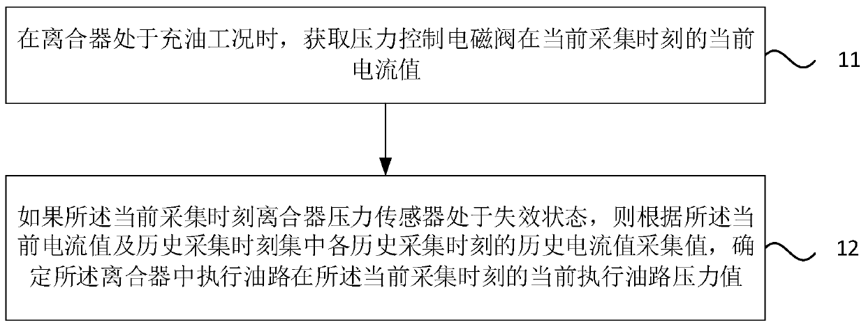
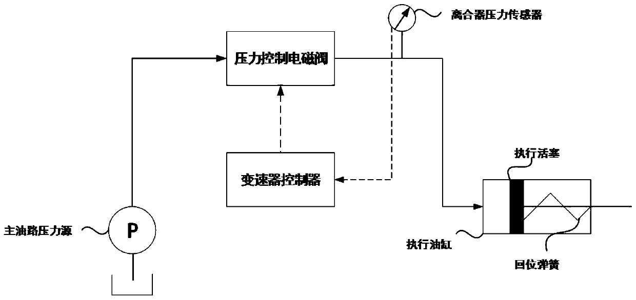
[0028] figure 1 It is a flow chart of a method for determining clutch pressure provided by Embodiment 1 of the present invention. This embodiment is applicable to the situation where the pressure sensor in the wet clutch pressure control system fails to estimate the oil circuit pressure. This method can be determined by the clutch pressure Determining means, the clutch pressure determining means can be implemented by software and / or hardware, the clutch pressure determining means can be configured on the computing device, for example, figure 2 It is a structural schematic diagram of a wet clutch pressure control system, which specifically includes the following steps:

[0029] Step 11. Acquire the current current value of the pressure control solenoid valve at the current collection time when the clutch is in the oil-filled working condition.

[0030] Among them, the oil-filled working condition can be understood as the main oil circuit pressure source controls the hydraulic...

Embodiment 2

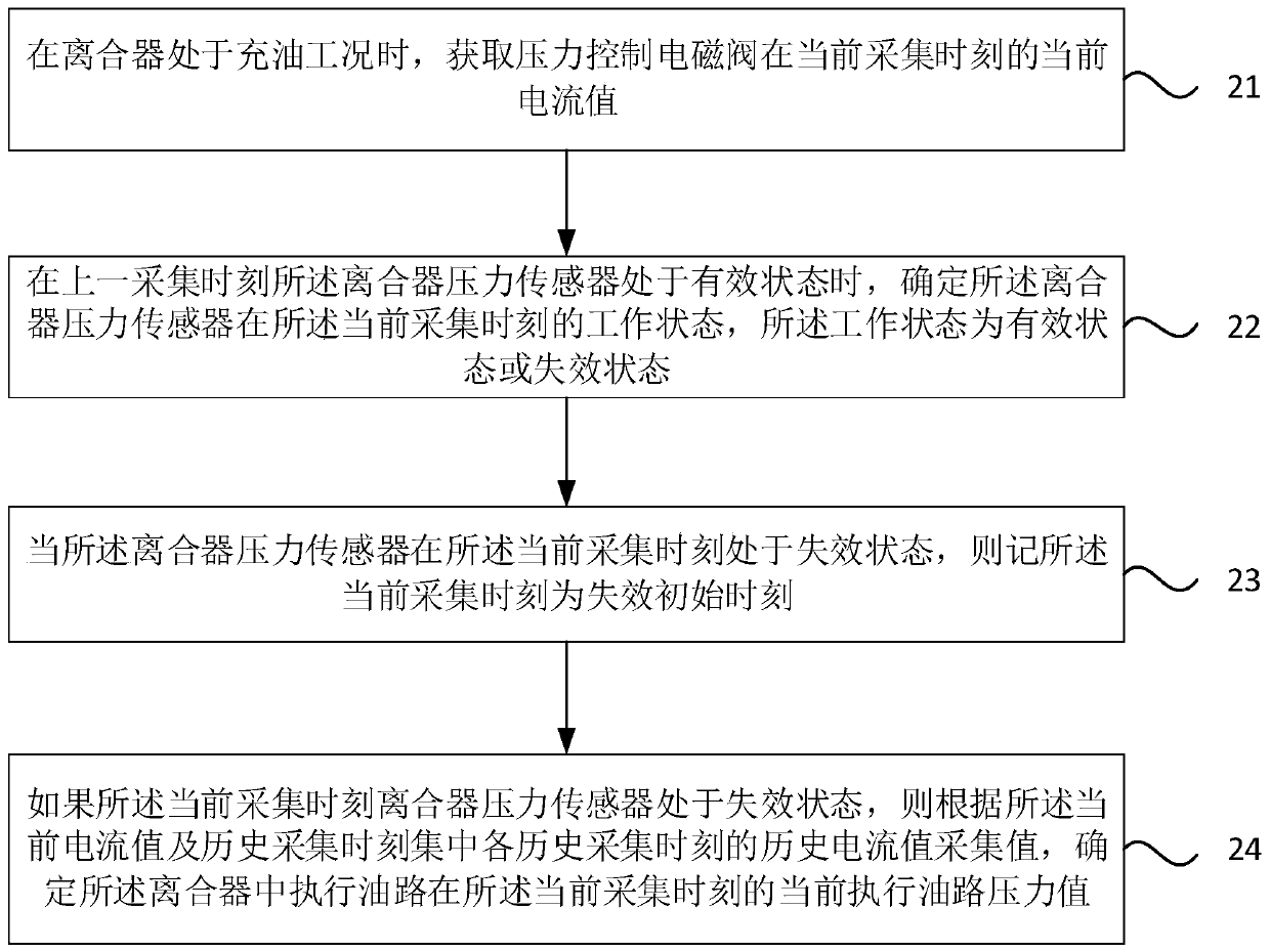
[0041] image 3 It is a flowchart of a method for determining clutch pressure provided by Embodiment 2 of the present invention. The technical solution of this embodiment is further refined on the basis of the above-mentioned technical solution, specifically including the following steps:

[0042] Step 21. Acquire the current current value of the pressure control solenoid valve at the current acquisition time when the clutch is in the oil-filling condition.

[0043] Step 22. When the clutch pressure sensor was in the valid state at the previous collection time, determine the working state of the clutch pressure sensor at the current collection time, and the working state is the valid state or the invalid state.

[0044] specific, Figure 4 A flow chart for determining the working state of the clutch pressure sensor at the current acquisition time is provided, which specifically includes the following steps:

[0045] Step 221. Obtain the current pressure value of the pressur...

Embodiment 3

[0058] Figure 5 It is a flow chart of a method for determining clutch pressure provided by Embodiment 3 of the present invention. The technical solution of this embodiment is further refined on the basis of the above-mentioned technical solution, specifically including the following steps:

[0059] Step 31. Acquire the current current value of the pressure control solenoid valve at the current acquisition time when the clutch is in the oil-filling condition.

[0060] Step 32. If the clutch pressure sensor is in failure state at the current collection time, acquire the historical current value and the corresponding historical execution oil circuit pressure value at each historical collection time.

[0061] Among them, the historical current value can be understood as the current given by the pressure control solenoid valve at the historical collection time, and the historical execution oil circuit pressure value can be understood as the pressure value in the execution cylinde...


PUM


Abstract

The embodiment of the invention discloses a clutch pressure determination method and device, a vehicle and a storage medium. The method comprises the steps that when a clutch is in an oil charging working condition, a current current value of a pressure control electromagnetic valve at a current acquisition moment is acquired; and if a clutch pressure sensor at the current acquisition moment is ina failure state, a current pressure value of an execution oil path in the clutch at the current acquisition moment is determined according to the current current value and a historical acquisition value at each historical acquisition moment. According to the technical scheme of the embodiment, the pressure of the execution oil path in the failure state is estimated according to parameters calculated under the normal state of the clutch pressure sensor, so that the problem that output of an oil pressure control signal of a transmission controller is unstable when a wet clutch pressure sensor fails under the oil charging working condition is solved, and the safety in the running process of the vehicle is improved.

Description

technical field [0001] The embodiments of the present invention relate to the technical field of clutch control, in particular to a method, device, vehicle and storage medium for determining clutch pressure. Background technique [0002] The wet clutch is a core part widely used in automatic transmissions of automobiles. The hydraulic system adjusts the torque transmitted by the clutch by controlling the oil pressure of the clutch executive oil circuit. [0003] The clutch pressure is usually collected by a pressure sensor installed on the hydraulic actuator oil circuit, and the signal is sent to the transmission controller. The transmission controller combines the current pressure of the clutch actuator oil circuit to control the various actuator components of the transmission according to the built-in operation logic. However, when the clutch pressure sensor fails or the connection line between the sensor and the controller is disconnected, the clutch pressure signal will ...

Claims


Application Information

Patent Timeline
IPC IPC(8): F16D25/0635F16D25/12F16D48/06
CPCF16D25/0635F16D25/14F16D48/066
Inventor 顾强刘振宇叶珂羽陈建勋康志军
Owner CHINA FIRST AUTOMOBILE
Why Eureka
Try Eureka