
A filter device and range hood using the filter device

A filter device and oil filter technology, which can be used in applications, oil fume removal, household stoves, etc. It can solve the problems of difficult cleaning, large filter size, and not greatly improved filtering effect, so as to achieve the lifting effect and improve the separation of grease efficiency effect

Active Publication Date: 2021-10-08
NINGBO FOTILE KITCHEN WARE CO LTD
View PDF8 Cites 0 Cited by
  • Summary
  • Abstract
  • Description
  • Claims
  • Application Information

AI Technical Summary

Problems solved by technology

[0005] However, the simple superimposition of such planar screens does not greatly improve the filtering effect, and generally the size of the filter screen is large, making it difficult to clean, and the multi-layer oil screen further increases the difficulty of cleaning

Method used


Image

  • A filter device and range hood using the filter device
  • A filter device and range hood using the filter device
  • A filter device and range hood using the filter device

Examples


Embodiment 1

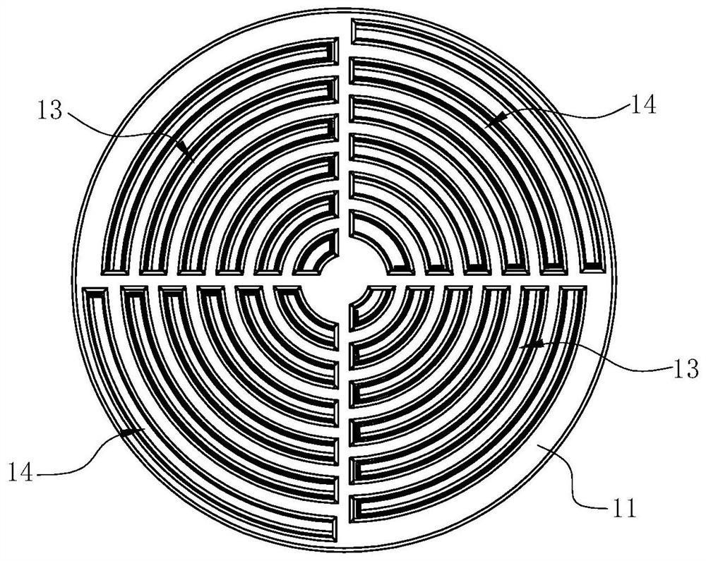
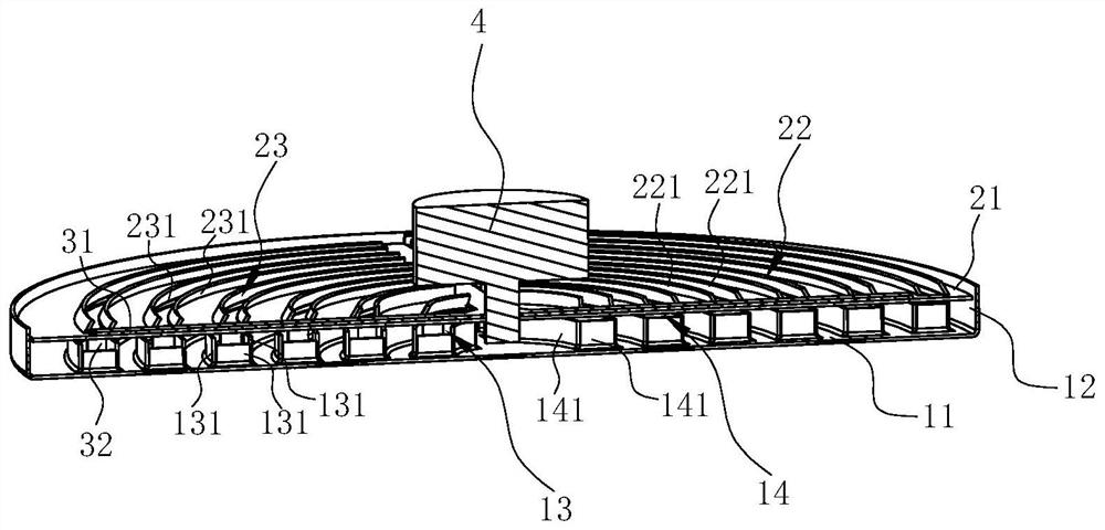
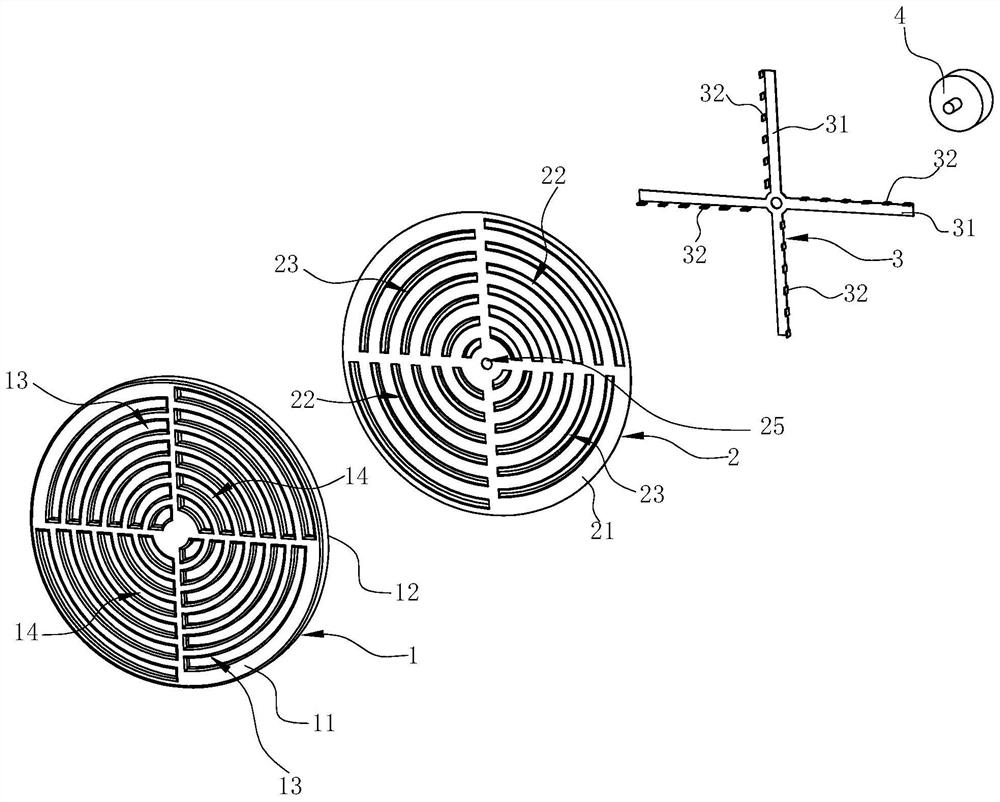
[0036] See Figure 1 ~ 3 One filter device includes a first filter net 1, a second oil filter die 2, an oil mesh screen 3, and a drive mechanism 4. The filtering device is mainly used for oil absorbing hood.

[0037] CombineFigure 4 The first filter noodle includes a total circular first network disk 11, and bends in the circumference of the first network disk 11 along the axial direction of the first network disk 11, opened in the first network. The first venting portion 13 and the second air inlet 14 on the disk 11, and the folding 12 is ring. The first vent 13 is curved, with at least two, the center symmetrical setting of the first network disk 11; the second air till 14 is curved, with at least two, the center symmetry setting of the first network disk 11. In the present embodiment, the first vent 13 has at least four, and has at least two on each side of the center of the first network disk 11, and the first air inlet 13 on the same side is along the first network disk 11. Th...

Embodiment 2

[0053] See Figure 9 ~ 12 In the present embodiment, the difference from the above-described embodiment is that the first air outlet 13 of the first filter net 1 has only one set, and each of the first air outlet 13 is close to the semi-circular, the second air opening 14 has only one set, and each of the second air port 14 is close to a semicircular shape, and the oil recess 15 has only one. Correspondingly, the third air port 22 of the second filter network 2 has only one set, and each of the third air port 22 is close to the semi-circular shape, and the fourth air port 23 has only one set, and each of the fourth venting ports 23 is close to a semicircular, and the connecting band 24 has only one. Oil network sieve 3 has only one sieve 31.

[0054] The operation principle of the filtration device of the present embodiment is in the same embodiment.


PUM


Abstract

The invention discloses a filtering device, which comprises a first oil filter net and a second oil filter net, the first oil filter net includes a first mesh pan, the second oil filter net includes a second net pan, and the first net pan is provided with a There are first air inlets and second air inlets arranged at intervals in the circumferential direction of the first grid tray, the first air inlets and the adjacent second air inlets are arranged alternately in the radial direction of the first grid tray, and the second grid tray There are third air inlets and fourth air inlets on the top, and they are arranged at intervals in the circumferential direction of the second grid tray, and the third air inlets and adjacent fourth air inlets are staggered in the radial direction of the second grid tray; the second The oil filter screen can rotate relative to the first oil filter screen so that the filter device is in an open state and a closed state. When the filter device is in an open state, the first air inlet and the second air inlet of the first oil filter screen are opened; when the filter device When in the closed state, the second oil filter screen blocks the first air inlet and the second air inlet of the first oil filter screen. Also disclosed is a range hood applied with the filter device.

Description

Technical field [0001] The present invention relates to a hood purification apparatus, in particular a filtration device, and an oil absorbing hood using the filter device. Background technique [0002] The oil hood has become one of the indispensable kitchen home appliances in modern families. The oil-hhoto machine is to operate with fluid kinetic principles, and the crankshaving fans inside the suction hood are used to use the filter filter section. Grease particles. The centrifugal fan includes a volute, an electric machine mounted in a volute in a volute and a rotating impeller. When the impeller is rotated, a negative pressure suction is generated in the center of the fan, and the fumes below the suction hood are suck in the fan. After the fan is accelerated, it is collected by the volute, and the discharge is guided outdoor. [0003] At present, the filter net of the suction hood in the market is poor, and many greases, the soot, the soot is finally accumulated in the impel...

Claims


Application Information

Patent Timeline
Patent Type & Authority Patents(China)
IPC IPC(8): F24C15/20
CPCF24C15/2035
Inventor 刘剑涛
Owner NINGBO FOTILE KITCHEN WARE CO LTD
Learn More