Novel chemical testing machine
A chemical test, a new type of technology, applied in the field of chemistry, can solve the problems of inconvenient cleaning of instruments, injury of experimental waste liquid, time-consuming and labor-intensive problems, and achieve the effect of automation efficiency, intuitive structure, and liberation of manpower
- Summary
- Abstract
- Description
- Claims
- Application Information
AI Technical Summary
Problems solved by technology
Method used
Image

Examples
Embodiment Construction
[0016] All features disclosed in this specification, or steps in all methods or processes disclosed, may be combined in any manner, except for mutually exclusive features and / or steps.
[0017] Combine below Figure 1-6 The present invention is described in detail, and for convenience of description, the orientations mentioned below are now stipulated as follows: figure 1 The up, down, left, right, front and back directions of the projection relationship itself are the same.
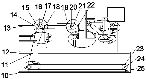
[0018] A kind of novel chemical testing machine of the device of the present invention comprises box body 10, and the first strut 13 is fixedly installed on the upper end face of described box body 10, and the PH testing device is arranged on the first strut 13, and the first strut 13 A rod 13 is provided with a liquid-taking device positioned at the right side of the pH testing device, a cleaning device is provided on the right side of the liquid-taking device, and a slideway 12 is fixedly installed on...
PUM
 Abstract
Description
Claims
Application Information