
Laser ranging sensor

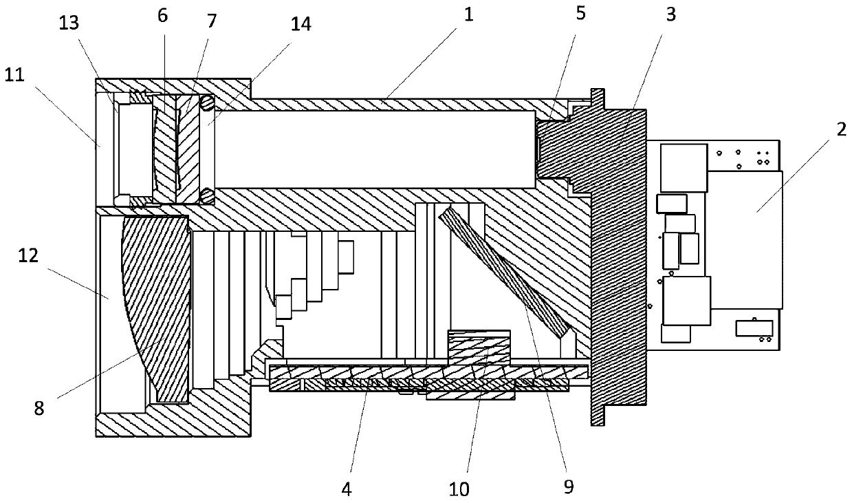
A laser ranging and sensor technology, applied in the field of ranging, can solve the problems of low accuracy, slow ranging response of laser ranging sensors, and easy to be interfered by smoke, dust and raindrops, etc., to achieve accurate ranging and enhanced transmission The effect of the ability of astigmatism

Pending Publication Date: 2020-05-15
SHENZHEN WEIRUI JINGKE ELECTRONICS
View PDF0 Cites 0 Cited by
  • Summary
  • Abstract
  • Description
  • Claims
  • Application Information

AI Technical Summary

Problems solved by technology

[0002] At present, the laser ranging sensors sold and used on the market are mainly composed of laser diodes, avalanche photodiodes and laser rangefinders. The laser diodes aim at the target and emit laser pulses. After being reflected by the target, the laser light is scattered in all directions, and part of the scattered light Returning to the sensor receiver, it is imaged on the avalanche photodiode after being received by the optical system, and the laser range finder calculates the measurement distance; because the laser is easily interfered by smoke, dust and raindrops, the existing laser range finder does not Strengthen the propagation ability of emitting laser and reflecting laser, so the existing laser ranging sensor has slow ranging response and low accuracy

Method used


Image

  • Laser ranging sensor
  • Laser ranging sensor
  • Laser ranging sensor

Examples


Embodiment Construction

[0033] The following will clearly and completely describe the technical solutions in the embodiments of the present invention with reference to the accompanying drawings in the embodiments of the present invention. Obviously, the described embodiments are only some of the embodiments of the present invention, not all of them. Based on the embodiments of the present invention, all other embodiments obtained by persons of ordinary skill in the art without making creative efforts belong to the protection scope of the present invention.

[0034] The object of the present invention is to provide a laser ranging sensor, which realizes fast and accurate ranging.

[0035] In order to make the above objects, features and advantages of the present invention more comprehensible, the present invention will be further described in detail below in conjunction with the accompanying drawings and specific embodiments.

[0036] A laser ranging sensor provided in an embodiment of the present inv...


PUM


Abstract

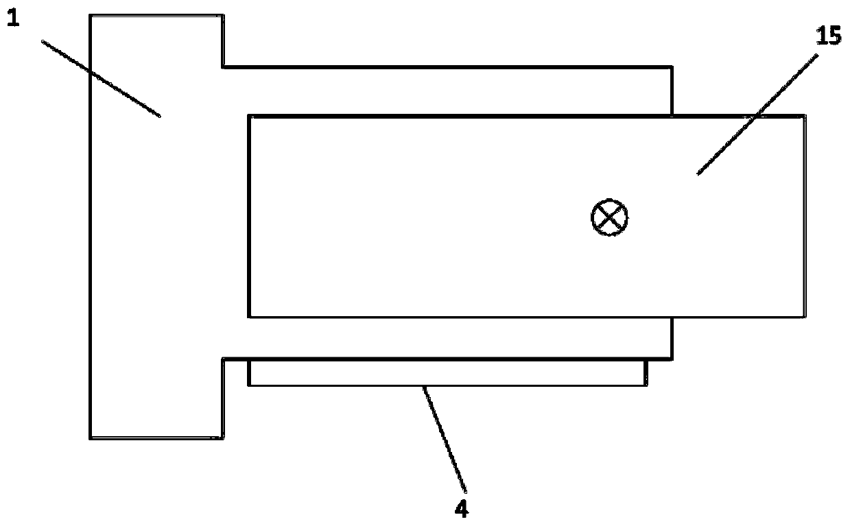
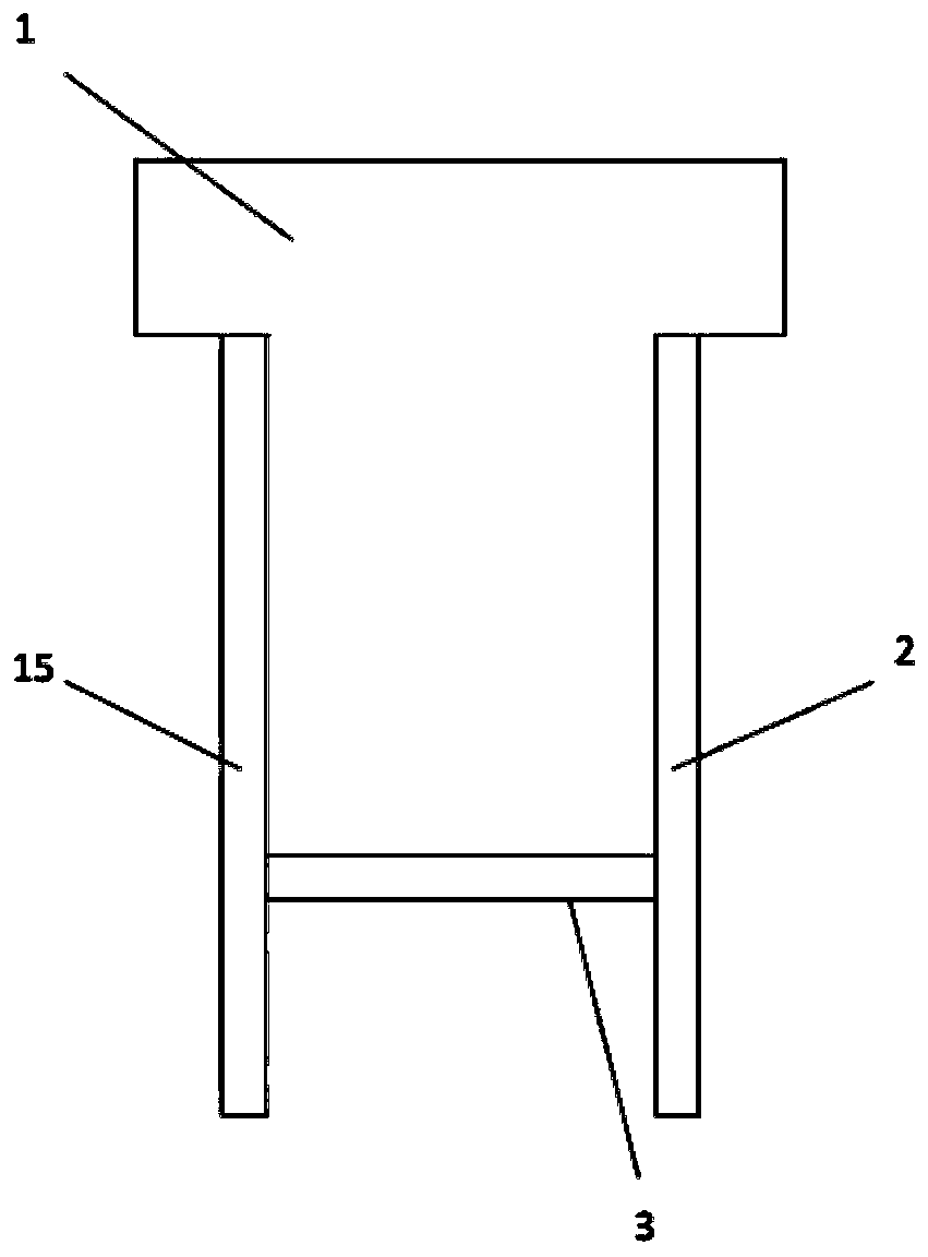
The invention discloses a laser ranging sensor. The sensor comprises an optical axis movement, a laser diode, a first small transmitting lens, a second small transmitting lens, a receiving lens, a reflecting mirror and an avalanche photodiode, the front end face of the optical axis movement is provided with a transmitting channel and a receiving channel. The emission channel is sequentially provided with the first small emission lens and the second small emission lens in the direction from the front end face to the rear end face of the optical axis movement. The laser diode is aligned with thetransmitting channel; and the receiving channel is sequentially provided with the receiving lens and the reflecting mirror along the direction from the front end surface to the rear end surface of the optical axis movement. According to the invention, the unique optical systems of the reflector, the first small transmitting lens and the second small transmitting lens are adopted, so that rapid and accurate distance measurement is realized.

Description

technical field [0001] The invention relates to the technical field of ranging, in particular to a laser ranging sensor. Background technique [0002] At present, the laser ranging sensors sold and used on the market are mainly composed of laser diodes, avalanche photodiodes and laser rangefinders. The laser diodes aim at the target and emit laser pulses. After being reflected by the target, the laser light is scattered in all directions, and part of the scattered light Returning to the sensor receiver, it is imaged on the avalanche photodiode after being received by the optical system, and the laser range finder calculates the measurement distance; because the laser is easily interfered by smoke, dust and raindrops, the existing laser range finder does not Strengthen the propagation ability of emitting laser and reflecting laser, so the existing laser ranging sensor has slow ranging response and low accuracy. Contents of the invention [0003] In order to overcome the de...

Claims


Application Information

Patent Timeline
IPC IPC(8): G01S17/08G01S7/481
CPCG01S7/481G01S17/08
Inventor 张丛林彭希
Owner SHENZHEN WEIRUI JINGKE ELECTRONICS
Learn More