Multi-phase transformer

A transformer and magnet technology, applied in the field of transformer equipment, can solve the problems of large volume, difficult installation, and large space occupation, and achieve the effects of reducing volume, reducing installation difficulty, and improving efficiency

Pending Publication Date: 2020-05-15
EGSTON ELECTRONICS ZHUHAI LTD
View PDF0 Cites 3 Cited by
  • Summary
  • Abstract
  • Description
  • Claims
  • Application Information

AI Technical Summary

Problems solved by technology

[0003] The existing problem of this kind of single-phase co-package inductance transformer is that the internal arrangement of this kind of single-phase co-package inductance tr

Method used


Image

  • Multi-phase transformer
  • Multi-phase transformer
  • Multi-phase transformer

Examples


Embodiment Construction

[0029] First embodiment of multi-phase transformer

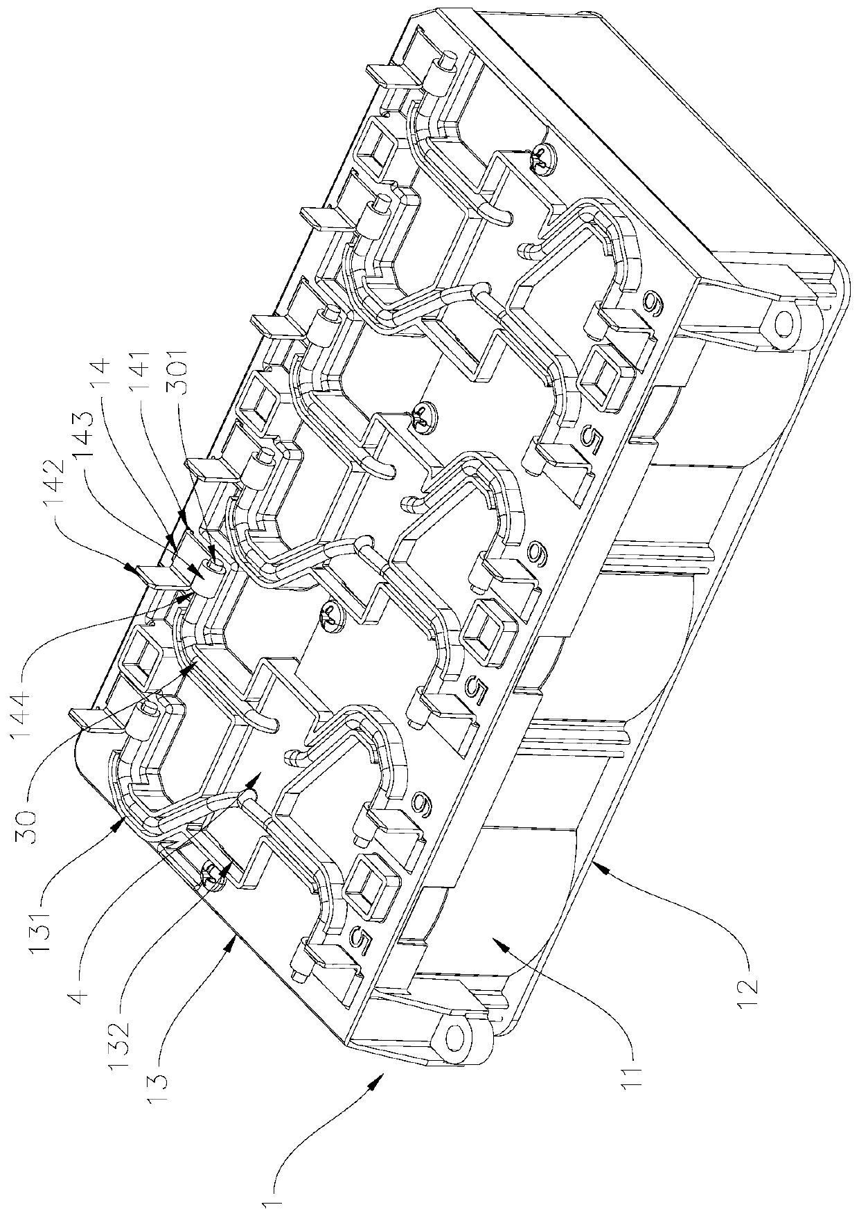
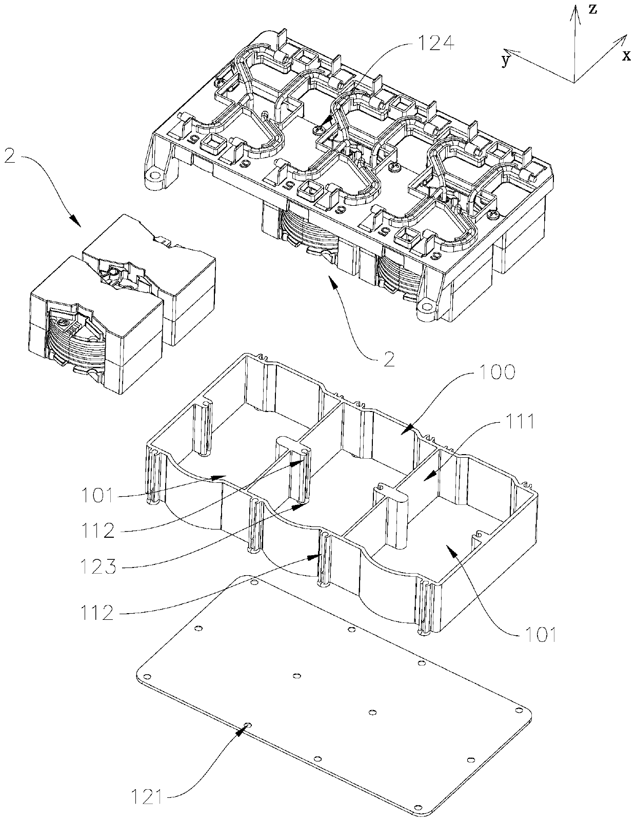
[0030] see figure 1 with figure 2 , figure 1 It is a structural diagram of the first embodiment of the multi-phase transformer of the present invention, figure 2 It is an exploded view of the structure of the first embodiment of the multi-phase transformer of the present invention. This embodiment is a three-phase transformer, and this embodiment is composed of a casing 1 , three inductive transformation units 2 , 12 conductive terminals 14 and a potting layer 4 potted in the casing 1 .

[0031] The casing 1 includes a bottom wall 12, a peripheral wall 11 and a cover 13 which are detachably connected, and a space 100 for accommodating three inductance transformer units 2 is formed between the bottom wall 12, the peripheral wall 11 and the cover 13, and the peripheral wall 11 also has a connection The two barrier walls 111 between the inner walls on opposite sides divide the space 100 into three mutually independent pla...


PUM


Abstract

A multi-phase transformer provided by the invention comprises a shell and an inductance transformation unit, the inductance transformation unit comprises a magnet assembly, a primary coil, a secondarycoil and an inductance coil; at least three placing spaces are formed in the shell, a blocking wall of the shell is blocked between two adjacent placing spaces, and an inductance transformation unitis arranged in each placing space; a first coil placement position and a second coil placement position are formed in the magnet assembly, the inductance coil is arranged in the first coil placement position, the primary coil and the secondary coil are arranged in the second coil placement position, and the inductance coil is connected with the primary coil in series. The shielding effect among the multi-phase inductance transformation units is ensured by the independent placement space; the primary coil and the secondary coil are concentrically arranged to reduce the volume of the magnet assembly, thereby reducing the volume of the multi-phase transformer; one-time resin encapsulation can be carried out in the shell, the heat dissipation performance of the product is guaranteed, the production efficiency is improved, only one-time positioning installation is needed when the multi-phase transformer is installed on a circuit, the installation difficulty is reduced, and the efficiency isimproved.

Description

technical field [0001] The invention relates to the technical field of transformer equipment, in particular to a multi-phase transformer. Background technique [0002] There is a single-phase co-packaged inductance transformer including a housing, a magnet assembly, a primary coil, a secondary coil and an inductance coil. The casing has a placement space, and the placement space is divided into an inductance space and a voltage transformation space by a barrier wall; the magnet assembly includes a first magnet, a second magnet, a third magnet and a fourth magnet, and the first magnet and the second magnet are relatively arranged on the inductance In the space, the third magnet and the fourth magnet are relatively arranged in the variable pressure space. The inductance coil is located between the first magnet and the second magnet; the first magnetic column and the second magnetic column are formed between the third magnet and the fourth magnet, the primary coil is wound on ...

Claims


Application Information

Patent Timeline
IPC IPC(8): H01F27/02H01F27/22H01F27/28H01F27/29H01F27/32H01F27/36H01F30/12
CPCH01F27/02H01F27/22H01F27/28H01F27/29H01F27/327H01F27/36H01F30/12
Inventor 龚新快王楚歆
Owner EGSTON ELECTRONICS ZHUHAI LTD
Why Eureka
Try Eureka