
Current bias adjusting method and device of direct-drive permanent magnet electric locomotive converter

A current bias, electric locomotive technology, applied in the conversion equipment for intermediate conversion to DC conversion, high-efficiency power electronic conversion, conversion of AC power input to DC power output, etc., can solve the problem of transformer temperature rise and other problems.

Active Publication Date: 2020-05-15
CRRC YONGJI ELECTRIC CO LTD
View PDF6 Cites 0 Cited by
  • Summary
  • Abstract
  • Description
  • Claims
  • Application Information

AI Technical Summary

Problems solved by technology

[0004] However, with the existing technology, the DC bias has not been fundamentally solved. The four-quadrant rectifier can operate stably, but the transformer still works at the bias point, and the temperature rise of the transformer and other problems caused by it have not been solved.

Method used


Image

  • Current bias adjusting method and device of direct-drive permanent magnet electric locomotive converter
  • Current bias adjusting method and device of direct-drive permanent magnet electric locomotive converter
  • Current bias adjusting method and device of direct-drive permanent magnet electric locomotive converter

Examples


Embodiment Construction

[0050] In order to make the purpose, technical solutions and advantages of the embodiments of the present invention clearer, the technical solutions in the embodiments of the present invention will be clearly and completely described below in conjunction with the drawings in the embodiments of the present invention. Obviously, the described embodiments It is a part of embodiments of the present invention, but not all embodiments. Based on the embodiments of the present invention, all other embodiments obtained by persons of ordinary skill in the art without creative efforts fall within the protection scope of the present invention.

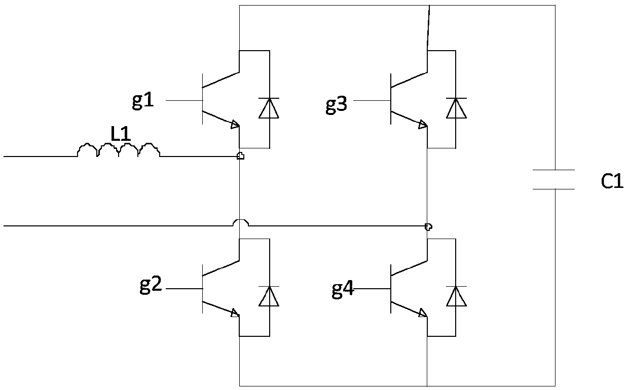
[0051] figure 1 The circuit diagram of the direct drive permanent magnet motor traction system provided for the embodiment of the present invention, such as figure 1 As shown, the direct drive permanent magnet motor traction system provided in this embodiment includes: a transformer 10, a pre-charging circuit 20, a four-quadrant rectifier 30, a b...


PUM


Abstract

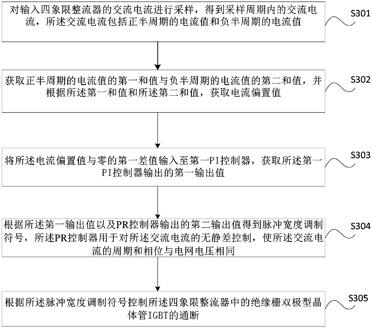
The embodiment of the invention provides a current bias adjusting method and device of a direct-drive permanent magnet electric locomotive converter, and the method comprises the steps of sampling analternating current inputted into a four-quadrant rectifier, and obtaining an alternating current in a sampling period, wherein the alternating current comprises a positive half-period current value and a negative half-period current value; obtaining a first sum value of the current values of the positive half cycle and a second sum value of the current values of the negative half cycle, and obtaining a current bias value according to the first sum value and the second sum value; inputting a first difference value between the current bias value and zero into a first PI controller to obtain a first output value outputted by the first PI controller; obtaining a pulse width modulation symbol according to the first output value and a second output value outputted by the PR controller; and controlling the on-off of an IGBT in the four-quadrant rectifier according to the pulse width modulation symbol. According to the method provided by the embodiment of the invention, the current bias at the transformer side can be fundamentally suppressed and eliminated, so that the influence of the current bias on the control of the four-quadrant converter is eliminated.

Description

technical field [0001] The invention relates to the electric locomotive converter technology, in particular to a method and equipment for adjusting the current bias of the direct-drive permanent magnet electric locomotive converter. Background technique [0002] The converter consists of two parts, a four-quadrant rectifier and an inverter. When the voltage bias of the four-quadrant rectifier occurs due to factors such as devices and controls, the four-quadrant converter will be unstable, and the IGBT device will deviate from its rated working area. At the same time, a large DC bias will be generated on the transformer, causing the transformer to work Point offset, temperature rise, etc. will seriously affect the normal operation of the rectifier and the normal operation of the electric locomotive, and at the same time cause damage to the transformer or reduce its service life. [0003] In the prior art, hardware filtering circuit design or software high-pass filter design ...

Claims


Application Information

Patent Timeline
IPC IPC(8): H02M5/42H02M7/219
CPCH02M5/42H02M7/219H02M1/0038Y02B70/10
Inventor 于森林张瑞峰苏鹏程张巧娟葸代其梁海刚张亚斌詹哲军邹会杰
Owner CRRC YONGJI ELECTRIC CO LTD
Learn More