
H-bridge drive circuit and current sensor based on H-bridge drive circuit

A bridge drive circuit and current sensor technology, applied in the field of sensing, can solve problems such as inapplicability, increased coil size, and large space, and achieve the effects of improving functional safety, large-range measurement, and high-precision measurement

Inactive Publication Date: 2020-05-15
陈玲
View PDF0 Cites 2 Cited by
  • Summary
  • Abstract
  • Description
  • Claims
  • Application Information

AI Technical Summary

Problems solved by technology

In order to increase the range of the sensor, it is necessary to increase the current size or the number of turns of the secondary side compensation coil, resulting in an increase in the size of the coil and an increase in the cost and size of the sensor
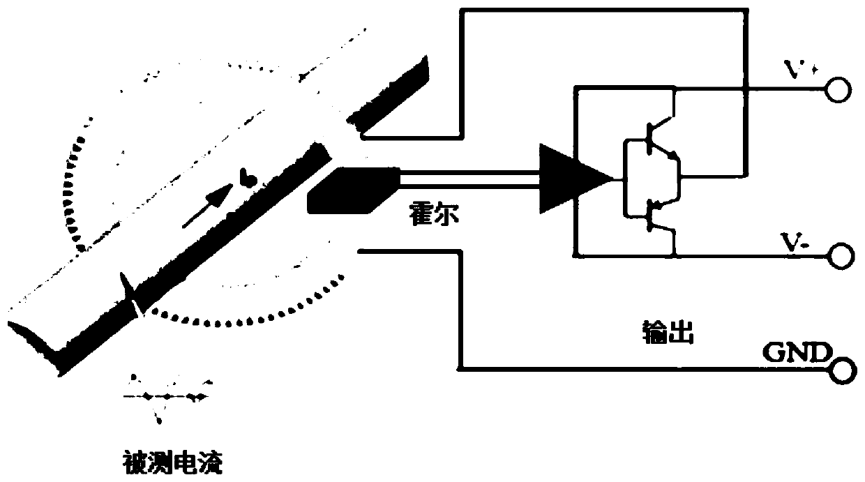
[0003] In the field of auto parts, almost no bipolar power supply is provided, so the traditional closed-loop Hall and closed-loop AMR technologies cannot be applied
Furthermore, the current range required by automobiles is above 1000 amperes. The aforementioned technologies require more space and higher costs as the range increases, and cannot meet the requirements of low cost and small size; further, products using these technologies do not Does not achieve functional safety and cannot meet automotive applications

Method used


Image

  • H-bridge drive circuit and current sensor based on H-bridge drive circuit
  • H-bridge drive circuit and current sensor based on H-bridge drive circuit
  • H-bridge drive circuit and current sensor based on H-bridge drive circuit

Examples


Embodiment Construction

[0034] Below in conjunction with accompanying drawing, technical scheme of the present invention is described in further detail:

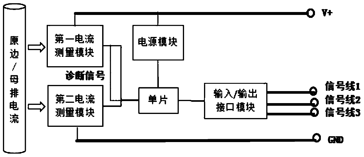
[0035] The present invention proposes an H-bridge driving circuit, comprising a first operational amplifier OP1, a second operational amplifier OP2, N first NPN transistors T1, N first PNP transistors T2, N second NPN transistors T3, N first Two PNP transistors T4, first to second resistors R1-R2 and sampling resistor Rs, N≥1; where,

[0036] The input terminal of the first operational amplifier OP1 is connected with the output terminal of the external magnetic sensitive unit, the output terminal of the first operational amplifier OP1 is connected with the base pole of the first NPN transistor T1 and the base pole of the first PNP transistor T2 respectively, the first The collector of the NPN transistor T1 is connected to the collector of the second NPN transistor T3, the emitter of the first NPN transistor T1 is connected to the emitter of the fir...


PUM


Abstract

The invention discloses an H-bridge driving circuit which comprises a first operational amplifier, a second operational amplifier, N first NPN triodes, N first PNP triodes, N second NPN triodes, N second PNP triodes, a first resistor, a second resistor and a sampling resistor. The invention further discloses a current sensor, the current sensor comprises a first current measurement module, a second current measurement module and a processor, and the first current measurement module comprises the H-bridge drive circuit, a magnetic sensitive unit and a coil. Under the condition of unidirectionalpower supply, high-precision measurement of bidirectional large current is realized, the cost is low, and the functional safety level of the sensor is improved.

Description

technical field [0001] The invention relates to the technical field of sensing, in particular to an H-bridge driving circuit and a current sensor based on the H-bridge driving circuit. Background technique [0002] Existing high-precision current measurement technologies include closed-loop Hall, closed-loop AMR, closed-loop TMR technology, or closed-loop fluxgate technology. Taking the closed-loop Hall technology as an example, it consists of an iron core with an air gap (and a secondary coil), a Hall unit, an operational amplifier, and a triode. Because the measured current is in two directions, the compensation coil needs compensation current in two directions, so the sensor needs a bipolar power supply. In order to increase the measuring range of the sensor, it is necessary to increase the current size or the number of turns of the secondary side compensation coil, resulting in an increase in the size of the coil and an increase in the cost and size of the sensor. [0...

Claims


Application Information

Patent Timeline
IPC IPC(8): H03K19/0175G01R1/30G01R15/20G01R15/18G01R19/25
CPCG01R1/30G01R15/18G01R15/202G01R19/2509H03K19/017518H03K19/01759
Inventor 陈玲
Owner 陈玲
Learn More