Charged micro-fog cyclone dust removal system for fine particles, and dust removal method thereof
A technology for fine particle and cyclone dust removal, which is applied in separation methods, chemical instruments and methods, and separation of dispersed particles, can solve the problems of low dust removal rate of fine particle dust, large water consumption of wet dust removal, etc. The effect of separation efficiency
- Summary
- Abstract
- Description
- Claims
- Application Information
AI Technical Summary
Problems solved by technology
Method used
Image
Examples
Embodiment 1
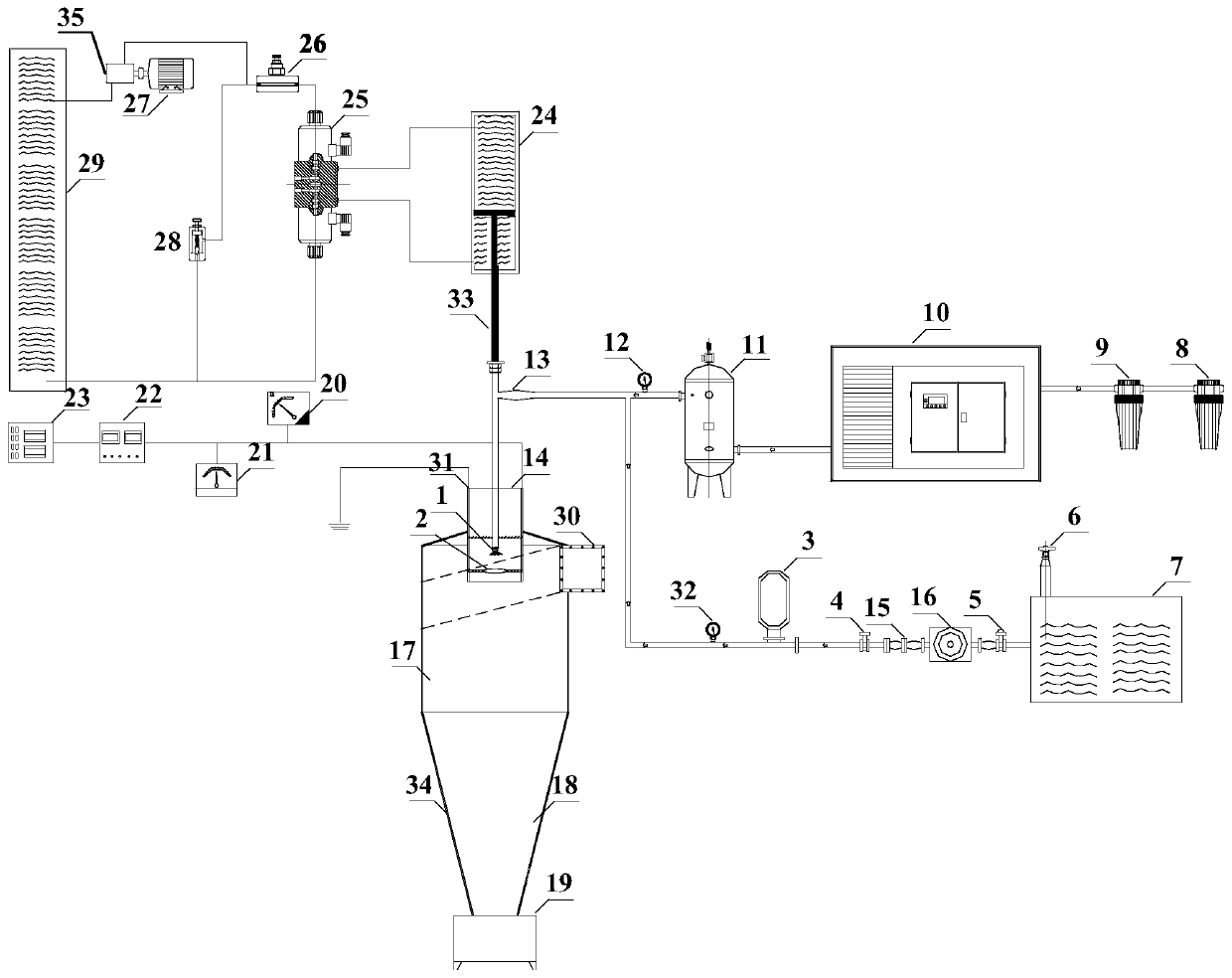
[0045] A charged micro-mist cyclone dust removal system for fine particles, its structure diagram is as follows figure 1 As shown, it includes hydraulic subsystem, charged micro-mist system and cyclone separation subsystem.
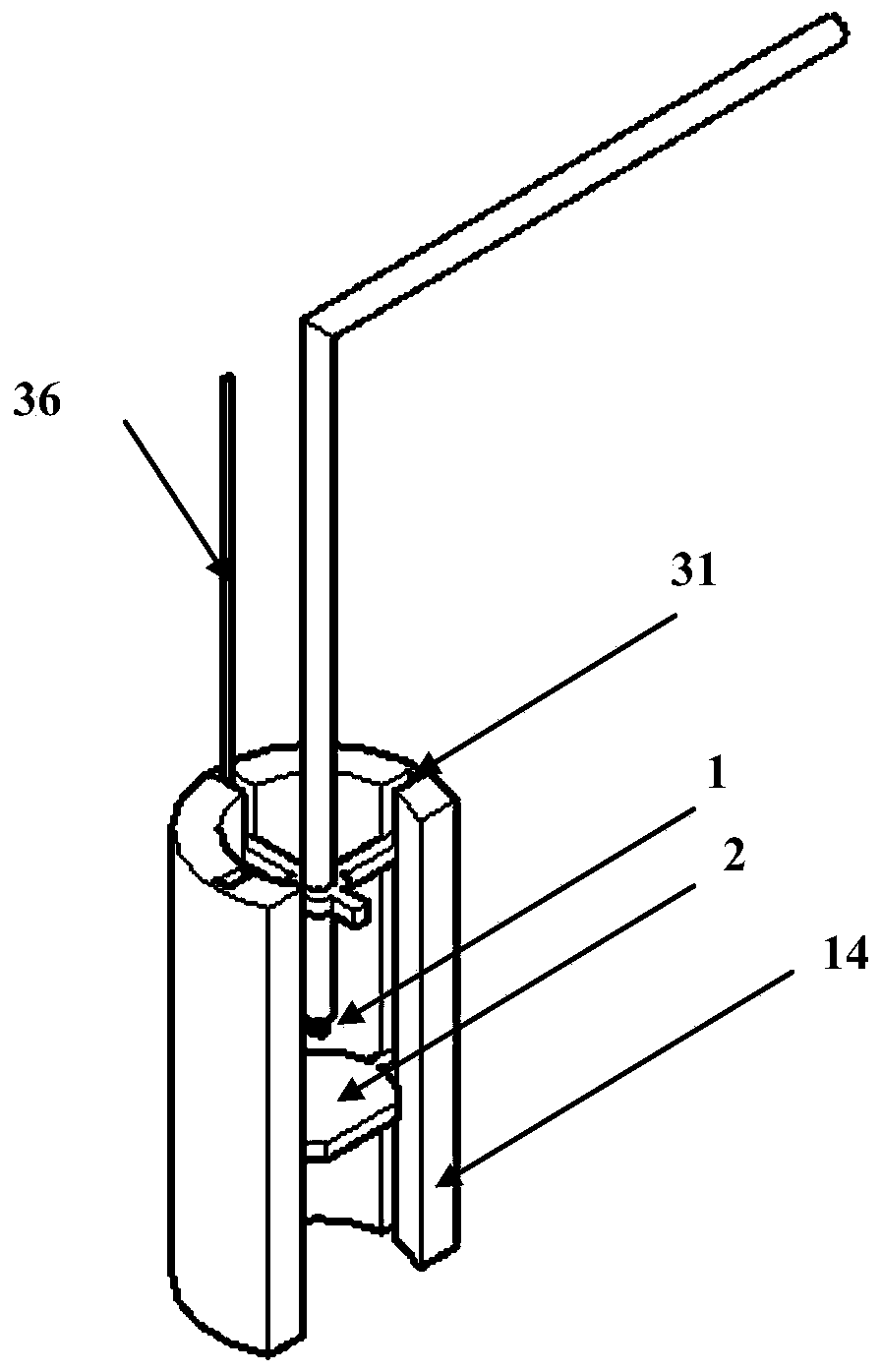
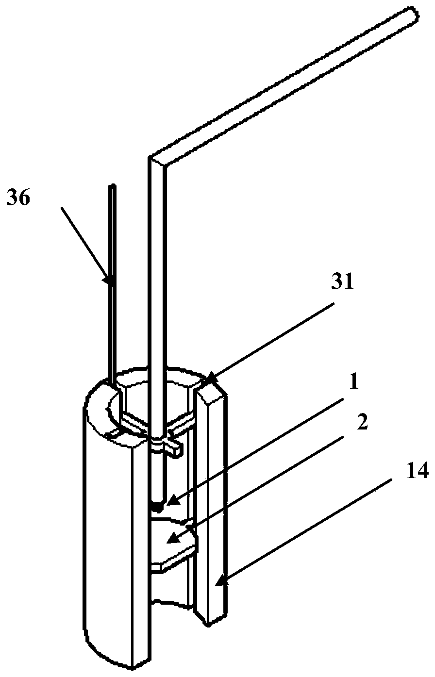
[0046] The charged micro-mist system includes a micro-mist system air circuit, a micro-mist system water circuit, a charge generation system, an atomizing nozzle 1, an annular electrode 2 and an exhaust cylinder 14;
[0047] The air path of the micro-mist system includes a screw air compressor 10, an air storage tank 11 and an air pressure gauge 12; the screw air compressor 10 is connected to the air storage tank 11 at one end, and the other end of the air storage tank 11 is connected to the air pressure gauge 12, and the air The output end of the pressure gauge 12 is used as the outlet of the gas path of the micro-mist system.
[0048] The air inlet of the screw air compressor 10 is connected in series with a T-level filter 9 and a C-level filter 8; the...
Embodiment 2
[0072] A charged micro-mist cyclone dust removal system for fine particles, same as embodiment 1.
[0073] A dust removal method of a charged micro-mist cyclone dust removal system for fine particles, the specific operation steps are as follows:
[0074] (1) Open the butterfly valve 5 first, the tap water will reach the atomizing nozzle 1 after passing through the voltage stabilizer compensator 3, and then turn on the mining screw air compressor 10, the air will pass through the C-level filter 8 and the T-level filter 9, and then pass through the screw air compressor. Enter the air storage tank 11 after the press 10, and start spraying now;
[0075] (2) By adjusting the flow valve 26 to control the oil flow, change the reversing valve 25 to change the direction, the oil enters the hydraulic cylinder 24, pushes the piston rod 33 to reciprocate, and puts the atomizing nozzle 1 along the inner wall of the exhaust cylinder. The exhaust tube slideway 31 slides down into the cyclon...
PUM
| Property | Measurement | Unit |
|---|---|---|
| particle diameter | aaaaa | aaaaa |
| dust removal efficiency | aaaaa | aaaaa |
Abstract
Description
Claims
Application Information
 - R&D
- Intellectual Property
- Life Sciences
- Materials
- Tech Scout
- Unparalleled Data Quality
- Higher Quality Content
- 60% Fewer Hallucinations
Browse by: Latest US Patents, China's latest patents, Technical Efficacy Thesaurus, Application Domain, Technology Topic, Popular Technical Reports.
© 2025 PatSnap. All rights reserved.Legal|Privacy policy|Modern Slavery Act Transparency Statement|Sitemap|About US| Contact US: help@patsnap.com


