Assembly process of blind hole tool with high precision requirement

An assembly process and high-precision technology, applied in the field of mechanical processing, can solve the problems of inability to meet hole accuracy and surface roughness, high dependence on the level of workers' assembly skills, and difficulty in meeting assembly requirements, so as to improve manufacturing processability and assembly. Qualified rate, quality stable and reliable effect

Active Publication Date: 2020-05-19
XIAN AERO ENGINE CONTROLS
View PDF6 Cites 3 Cited by
  • Summary
  • Abstract
  • Description
  • Claims
  • Application Information

AI Technical Summary

Problems solved by technology

This method is very uneconomical and difficult to meet the assembly requirements. The reason is that after the processing of the parts is completed, the adjustment assembly method is required to assemble the parts together, and the adjustment assembly method can only be used for multiple high-precision shapes and positions at one time. One of the tolerance requirements is adjusted separately, which is too dependent on the assembly skill level of the workers, which is also one of the main reasons for the unqualified assembly
[0003] In actual production, coordinate boring equipment is used for the finishing of datum C. Although the method of assembly first and then machining can meet the shape and position accuracy of datum C, it will interfere with the support plate 2 during machining because the diameter of the main shaft is too large.
And if the boring tool passes through the support plate 2 Through hole 7 to process on support 3 Blind hole 8, the largest diameter of the shank can only be selected The length can only be processed with an extended tool bar (calculated, the length of the tool bar is not less than 330mm). Because the length-to-diameter ratio of the boring tool bar is too large, problems such as vibration and tool gap will inevitably occur during processing, which cannot meet the hole accuracy and surface roughness. requirements, and it is also easy to damage the boring tool
Therefore, the processing method is poor in manufacturability

Method used


Image

  • Assembly process of blind hole tool with high precision requirement
  • Assembly process of blind hole tool with high precision requirement
  • Assembly process of blind hole tool with high precision requirement

Examples


Embodiment Construction

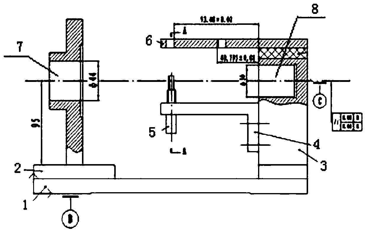
[0055] The invention provides an assembly process of blind hole tooling with high precision requirements, which specifically includes the following steps:

[0056] 1) The base 1 blank is provided in the form of No. 45 steel sheet. When rough machining, leave 0.5-0.6mm allowance in the thickness direction (board size 17×124×336), and leave 0.3mm grinding allowance for the front side, and normalize the material. After quenching, cleaning, aging heat treatment, rough grinding, fine grinding on both sides of the thickness and alignment, to fully eliminate the deformation after heat treatment, to ensure that the parallelism of the two sides of the thickness is within 0.01mm, and the perpendicularity to the alignment reference plane is within 0.005mm;

[0057] 2) The blank of the support plate 2 is provided in the form of No. 45 steel forgings. During rough machining, the full shape is milled, leaving 0.4-0.5mm allowance in the thickness direction, and 0.3mm allowance on the bottom s...


PUM

PropertyMeasurementUnit
verticalityaaaaaaaaaa

Abstract

The invention belongs to the field of machining, and relates to an assembly process of a blind hole tool with a high precision requirement. The assembly process comprises the following steps of 1) processing a base, and ensuring the parallelism of two surfaces of the thickness of the base and the perpendicularity with an alignment reference surface; 2) processing a support plate, and ensuring theparallelism of the two surfaces of the thickness of the support plate and the perpendicularity with the bottom surface; 3) processing a support, and ensuring the parallelism of the two of the thickness of the support and the perpendicularity with the bottom surface; 4) processing a positioning plate; 5) processing a guide plate; 6) assembling the base, the support and the positioning plate into anintegral structure, fixing the integral structure on a workbench of the coordinate boring machine, machining a blind hole in the support by adopting a boring cutter, axially lifting the boring cutter, assembling the support plate on the base, replacing the boring cutter, and machining a through hole in the support plate on the support plate; and 7) assembling the guide plate on the support by anadjusting assembly method. According to the assembly process of the blind hole tool with the high precision requirement, the requirement for the assembly form and location tolerance is met, dependenceon the skill level of workers is reduced, and the assembly qualification rate can be greatly increased.

Description

technical field [0001] The invention belongs to the field of mechanical processing, and relates to an assembly process of tooling, in particular to an assembly process of blind hole tooling with high precision requirements. Background technique [0002] The structure of the electric spark fixture is as follows figure 1 As shown, a plurality of parts including a base 1, a support plate 2, a support 3, a positioning plate 4 (the positioning plate 4 is provided with a latch 5) and a guide plate 6. Among them, the center line (reference C) of the through hole 7 of Ф44mm on the support plate 2 and the blind hole 8 of Ф30mm on the support 3 (reference C) is opposite to the installation surface of the EDM fixture (reference B) and the front (reference surface H, such as figure 2 The parallelism shown) is not greater than 0.01mm; the symmetry of the two grooves on the guide plate 6 to the reference C is not greater than 0.01mm, and the perpendicularity to the reference B is not gr...

Claims


Application Information

Patent Timeline
Patent Type & Authority Applications(China)
IPC IPC(8): B23P15/00
CPCB23P15/00
Inventor 李亚云贾双良徐辰杜龙龙王建武王锋
Owner XIAN AERO ENGINE CONTROLS
Why Eureka
Try Eureka