Device for cleaning sediments in machine tool water tank

A machine tool water tank and sediment technology, applied in the direction of cleaning hollow objects, cleaning methods and utensils, metal processing mechanical parts, etc., can solve the problems of occupying machine tool processing time, low cleaning efficiency, time-consuming and laborious, etc., to reduce enterprise losses and save time. , the effect of avoiding machine downtime

Active Publication Date: 2020-05-19
阜宁泰利泵业有限公司
View PDF8 Cites 7 Cited by
  • Summary
  • Abstract
  • Description
  • Claims
  • Application Information

AI Technical Summary

Problems solved by technology

When cleaning the water tank, the machine tool needs to stop working, and many parts installed on the water tank are removed. After cleaning, these parts need to be reinstalled. Some parts, especially the pipelines, will have water seepage and leakage after reinstallation, and the cleaning process is time-consuming and laborious. , the cleaning efficiency is extremely low, and it will also take up machine tool processing time and bring unnecessary losses to the enterprise. Therefore, in view of the above status quo, it is urgent to develop a device for cleaning machine tool water tank sediments to overcome the shortcomings in current practical applications

Method used


Image

  • Device for cleaning sediments in machine tool water tank
  • Device for cleaning sediments in machine tool water tank
  • Device for cleaning sediments in machine tool water tank

Examples


Embodiment 1

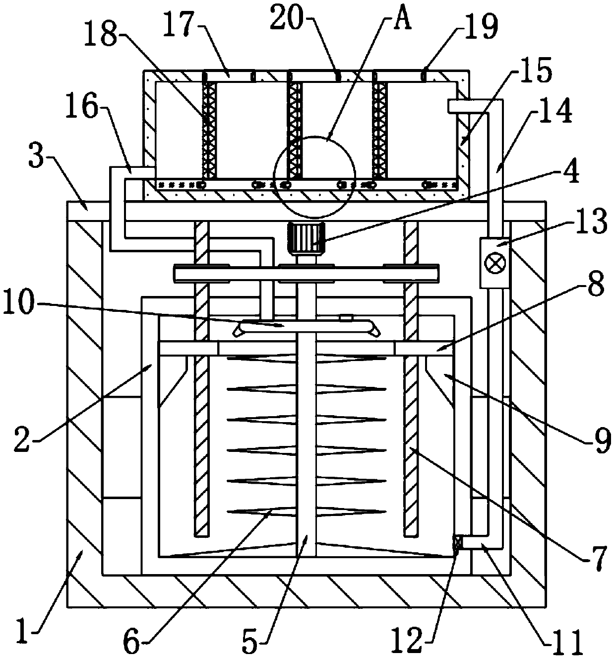
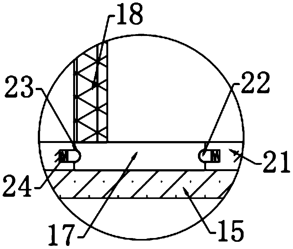
[0025] see Figure 1-3 , in an embodiment of the present invention, a device for cleaning machine tool water tank sediments includes a support frame 1, a water tank 2 is fixedly connected to the inner side of the support frame 1, and a chip removal mechanism is arranged on the inner side of the water tank 2. A top plate 3 fixedly connected to the support frame 1 is provided on the side, and a purification mechanism for collecting sediment is provided on the top of the top plate 3 .

Embodiment 2

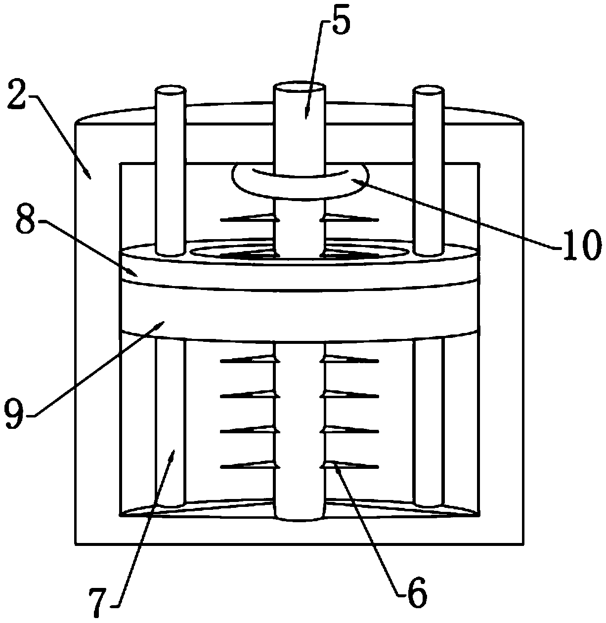
[0027] In this embodiment, the chip removal mechanism includes a push plate 8 arranged inside the water tank 2, and the bottom of the push plate 8 is fixedly connected with a scraper 9 that is attached to the inner side of the water tank 2. The left and right sides of the push plate 8 The inner sides of both ends are threadedly connected with a threaded rod 7, which is connected to the driving mechanism arranged at the bottom of the top plate 3. By setting the scraper 9 and moving up and down the scraper 9, the scraper attached to the box wall can be removed. The sediment is scraped off to facilitate the collection of the sediment.

[0028] In this embodiment, the drive mechanism includes a motor 4 bolted to the bottom of the top plate 3, the output end of the motor 4 is connected to the rotating rod 5, and the outer sides of the rotating rod 5 and the threaded rod 7 are fixedly connected with pulleys. , the pulleys are connected by a belt, and the bottom of the rotating rod 5...


PUM


Abstract

The invention relates to the technical field of machine tool-related equipment, in particular to a device for cleaning sediments in a machine tool water tank. The device includes a support frame, a water tank is fixedly connected to the inner side of the support frame, a chip removal mechanism is arranged on the inner side of the water tank, a top plate fixedly connected with the support frame isarranged on the upper side of the water tank, and a purification mechanism for collecting the sediments is arranged at the top of the top plate. According to the device for cleaning the sediments in the machine tool water tank, a scraping plate is arranged, the up and down movement of the scraping plate can be used for scraping down the sediments attached to the tank wall, and the sediments can beconveniently collected; a crushing blade is arranged to crush impurities scraped from the tank wall to avoid the pipe blockage due to the excessive volume of the impurities, and the stability of thepurification process is ensured; a spraying pipe is arranged to wash the scraping plate and the tank wall by using the purified water, and the device can clean up the sediments more thoroughly; and the purification mechanism is arranged, the sediments in the water tank can be collected, and the sediments in the water tank can be automatically cleaned without removing other parts installed on the water tank.

Description

technical field [0001] The invention relates to the technical field of machine tool-related equipment, in particular to a device for cleaning sediment in a water tank of a machine tool. Background technique [0002] At present, most machine tools need cutting fluid lubrication and cooling, and most machine tools need to be equipped with cutting fluid cooling and purification devices, that is, water tanks or oil tanks. There are a large number of components installed on the water tank, such as: oil cooler, filter, liquid level detection device, degreasing device, and various pump sets for the machine tool. The sediment at the bottom of the water tank needs to be thoroughly cleaned during maintenance of these devices (including machine tool processing). Chips, muddy sediments and other sundries produced by the mixture of grease and fine powder chips) to prevent sundries from clogging the liquid supply pump, pipelines and the impact of more cutting fluid impurities on machining...

Claims


Application Information

Patent Timeline
Patent Type & Authority Applications(China)
IPC IPC(8): B23Q11/00B08B9/087B08B3/04B01D29/01B01D29/58B01D29/64
CPCB01D29/01B01D29/58B01D29/64B08B3/04B08B9/087B23Q11/0042
Inventor 吴东芝
Owner 阜宁泰利泵业有限公司
Why Eureka
Try Eureka