Electroplating processing technology for piston rod manufacturing

A processing technology and piston rod technology, which is applied in the field of piston rod manufacturing and electroplating processing technology, can solve the problems of incomplete electroplating on the surface of the piston rod and difficulty in penetrating the surface of the electroplating solution, etc., so as to improve the electroplating efficiency, improve the electroplating surface and reduce the working time. Effect

Active Publication Date: 2020-05-19
上海太同电镀有限公司
View PDF6 Cites 2 Cited by
  • Summary
  • Abstract
  • Description
  • Claims
  • Application Information

AI Technical Summary

Problems solved by technology

[0007] In view of the problems in the prior art, the object of the present invention is to provide a piston rod manufacturing electroplating process, which solves the problem that the piston rod will swing within a certain range when it is inserted into the electroplating solution, and the piston rod will gradually stop after freely swinging in the electroplating bath. The piston rod is still in the electroplating solution, and the surface of the electroplating solution has a certain tension, which is difficult to penetrate into the small holes on the surface of the piston rod, resulting in the technical problem of incomplete electroplating on the surface of the piston rod

Method used


Image

  • Electroplating processing technology for piston rod manufacturing
  • Electroplating processing technology for piston rod manufacturing
  • Electroplating processing technology for piston rod manufacturing

Examples


Embodiment 1

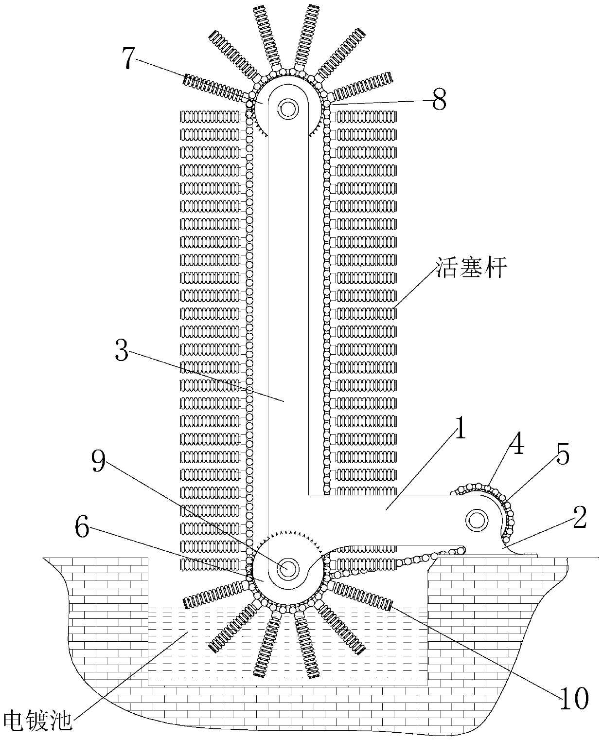
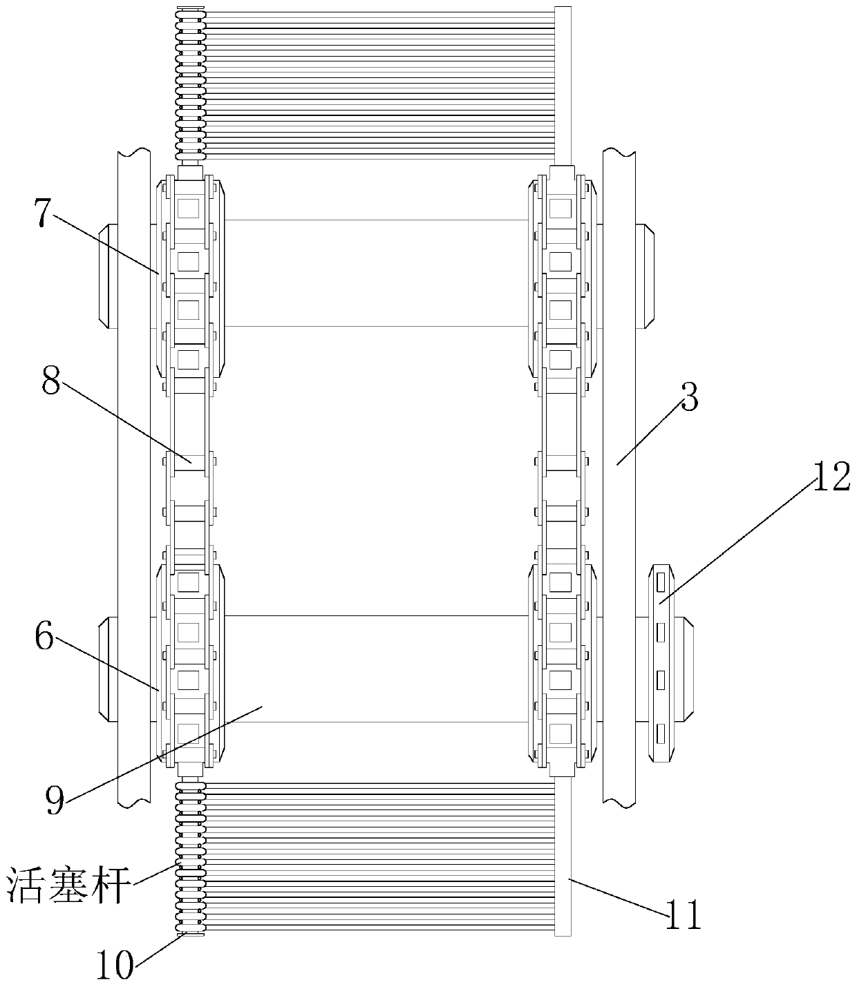
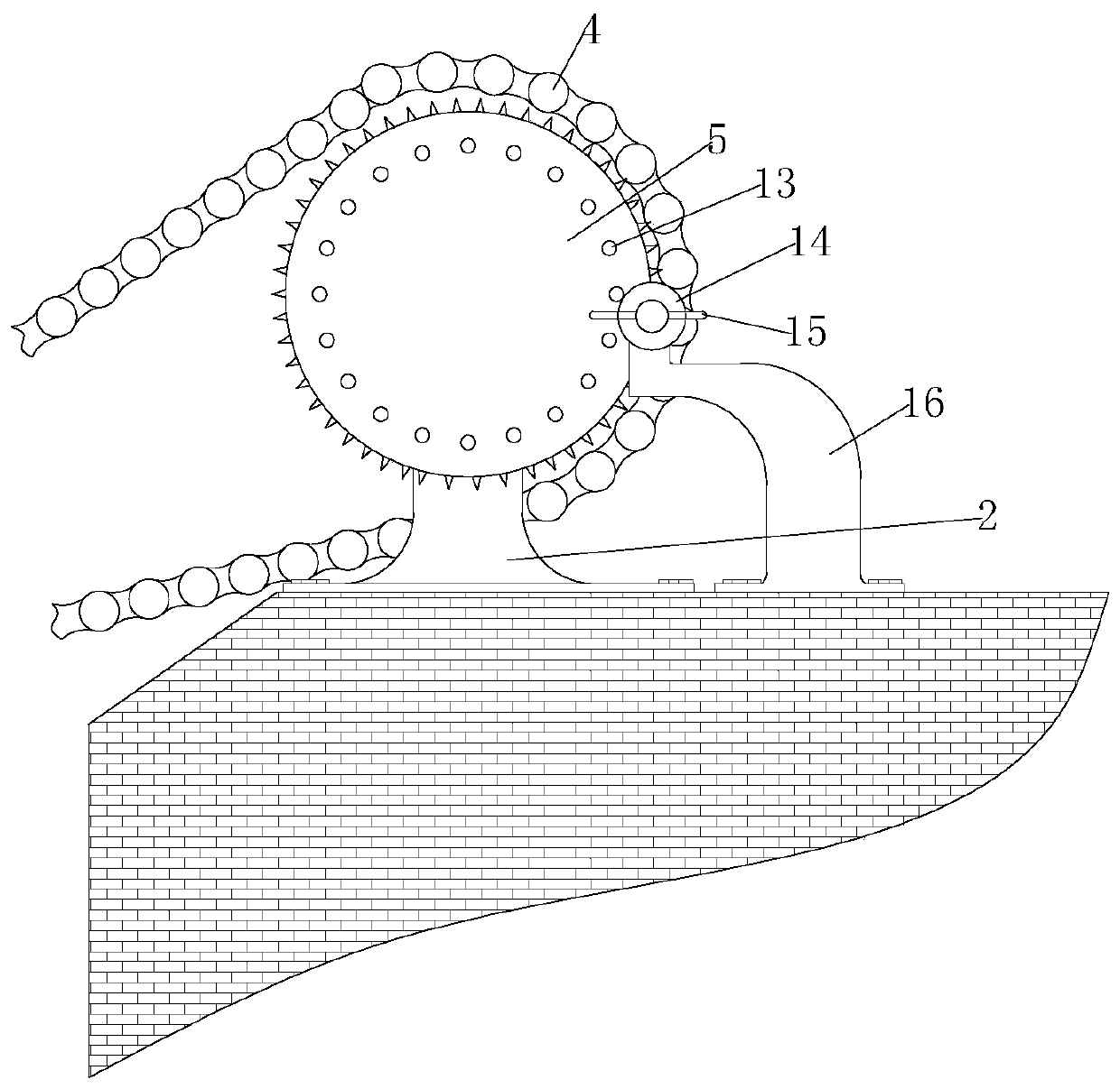
[0042] see Figure 1-9 , is a schematic diagram of the overall structure of a piston rod manufacturing electroplating process; a piston rod manufacturing electroplating process is applied to the piston rod manufacturing process, and the formed piston rod is placed in the electroplating pool for electroplating, and the piston rod manufacturing The electroplating process is completed by a piston rod manufacturing electroplating processing device. The piston rod manufacturing electroplating processing device includes a foot 2 fixed on the edge of the electroplating pool; there are two foot 2 in total, and the two foot 2 are fixed front and rear On the edge of the electroplating pool, the top of each foot 2 is provided with a horizontally fixed first support arm 1, and the top of the first support arm 1 is fixed with a frame 3 standing upright on the bottom of the electroplating pool, and the tops of the two frames 3 are And the bottom end of the frame 3 is respectively equipped w...


PUM


Abstract

The invention discloses an electroplating processing technology for piston rod manufacturing, and relates to the technical field of plate processing. An electroplating processing device for piston rodmanufacturing comprises bottom feet fixed to the edge of an electroplating pool, wherein the two bottom feet are arranged and are fixed to the edge of the electroplating pool front and back; a firstsupporting arm which is horizontally fixed is arranged at the top end of each bottom foot; a rack which is erected on the bottom surface of the electroplating pool is fixed to the top end of each first supporting arm; and a transmission shaft rod is mounted at the top ends of the two racks and the bottom ends of the racks correspondingly. According to the electroplating processing technology for piston rod manufacturing, the two ends of each piston rod are clamped and fixed, so that every two adjacent piston rods can still be firm and reliable when moving in electroplating liquid of the electroplating pool; and the multiple piston rods are sequentially and circularly conveyed into the electroplating pool through a second transmission chain, so that the working time consumed by a conveyingdevice during reciprocating return is shortened, and the electroplating efficiency of the piston rods is improved.

Description

technical field [0001] The invention relates to the technical field of piston rod processing, in particular to an electroplating process for manufacturing a piston rod. Background technique [0002] The piston rod is a connecting part that supports the work of the piston. Most of them are used in the cylinder and cylinder motion actuators. It is a moving part with frequent movements and high technical requirements. Taking the hydraulic cylinder as an example, it consists of cylinder barrel, piston rod (cylinder rod), piston, end cover, support ring and other parts. The quality of its processing directly affects the life and reliability of the entire product, and the smoothness of the piston rod surface directly affects the working performance of the entire hydraulic cylinder. [0003] Existing, in order to improve the smoothness of the piston rod surface, the finished piston rod surface is often electroplated. Patent No. CN201110375741.4 discloses a piston rod surface elect...

Claims


Application Information

Patent Timeline
IPC IPC(8): C25D7/00C25D17/08C25D21/10
CPCC25D7/00C25D17/08C25D21/10
Inventor 高峰王彦洲
Owner 上海太同电镀有限公司
Why Eureka
Try Eureka