Bedding mortar mold for assisting connection of prefabricated cover beam and prefabricated stand column

A prefabricated cover and column technology, which is applied in bridges, bridge construction, erection/assembly of bridges, etc., can solve the problems of reduced waste rate of sitting grouting molds, poor compatibility of sitting grouting molds, unavailable sizes, etc., to avoid grout leakage , not easy to angle deviation, high stability effect

Inactive Publication Date: 2020-05-19
绍兴市城投建筑工业化制造有限公司 +1
View PDF5 Cites 2 Cited by
  • Summary
  • Abstract
  • Description
  • Claims
  • Application Information

AI Technical Summary

Problems solved by technology

[0006] In order to overcome the problem of the high flatness of the top surface of the prefabricated column during the connection process of the prefabricated column and the prefabricated cover beam in the prior art, the present invention cannot directly arrange the slurry, and the slurry mold that assists the positioning of the slurry needs to be of the same size. Prefabricated columns and prefabricated cover beams are used together, and the poorly compatible sitting mold cannot be applied to the installation process of prefabricated columns and prefabricated cover beams with inconsistent sizes, which leads to the technical problem of high scrap rate of the sitting mold. Auxiliary prefabricated cover beam and prefabricated column connection sitting slurry mold, the sitting slurry mold spliced ​​by size-adjustable side forms has high versatility. When the size of prefabricated column and prefabricated cover beam changes, select the corresponding size The side molds are spliced ​​to form a slurry mold to realize the slurry arrangement on the top surface of the prefabricated column. The scrap rate of the slurry mold is greatly reduced and the production cost is effectively saved.

Method used


Image

  • Bedding mortar mold for assisting connection of prefabricated cover beam and prefabricated stand column
  • Bedding mortar mold for assisting connection of prefabricated cover beam and prefabricated stand column
  • Bedding mortar mold for assisting connection of prefabricated cover beam and prefabricated stand column

Examples


Embodiment

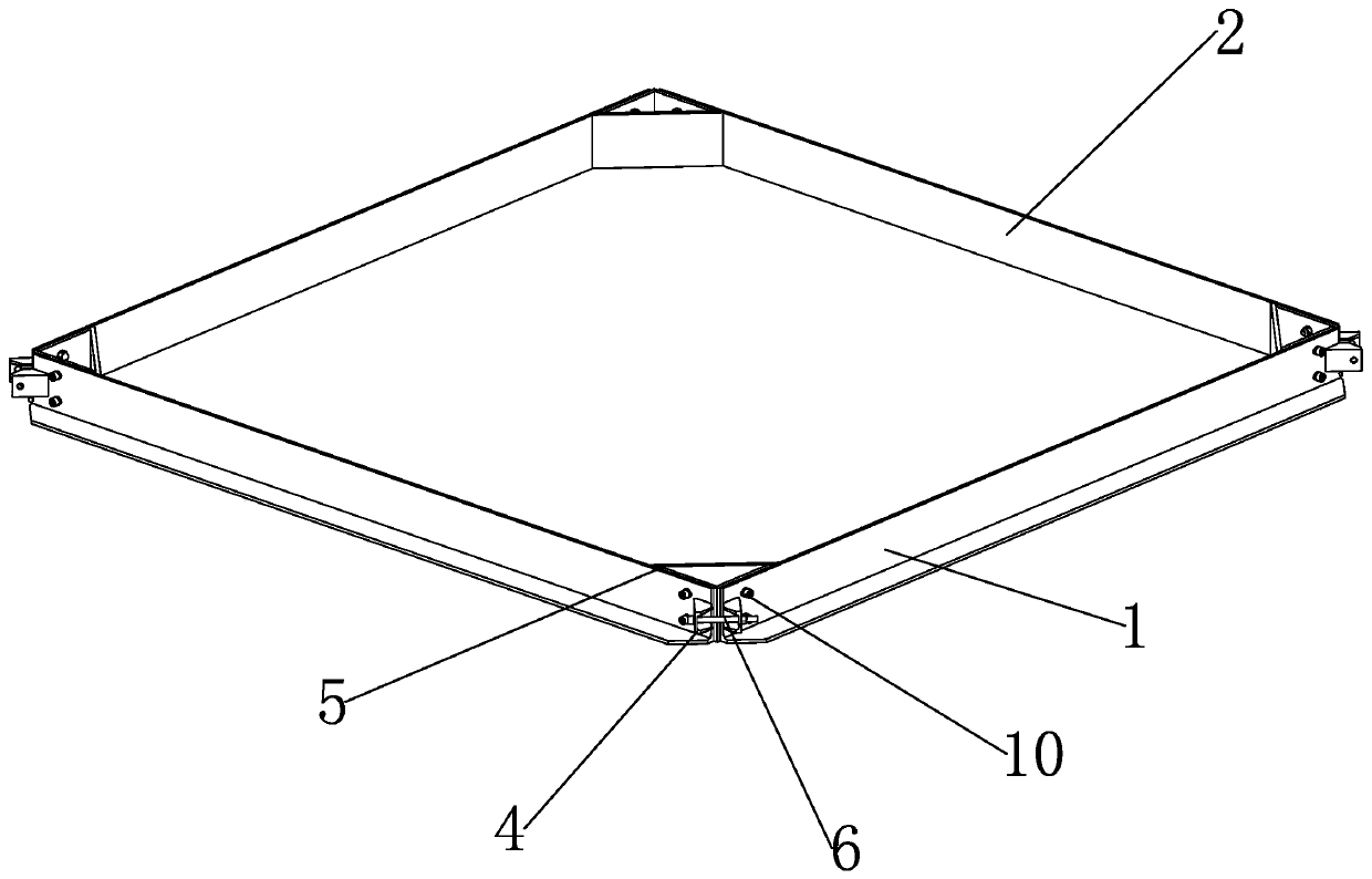
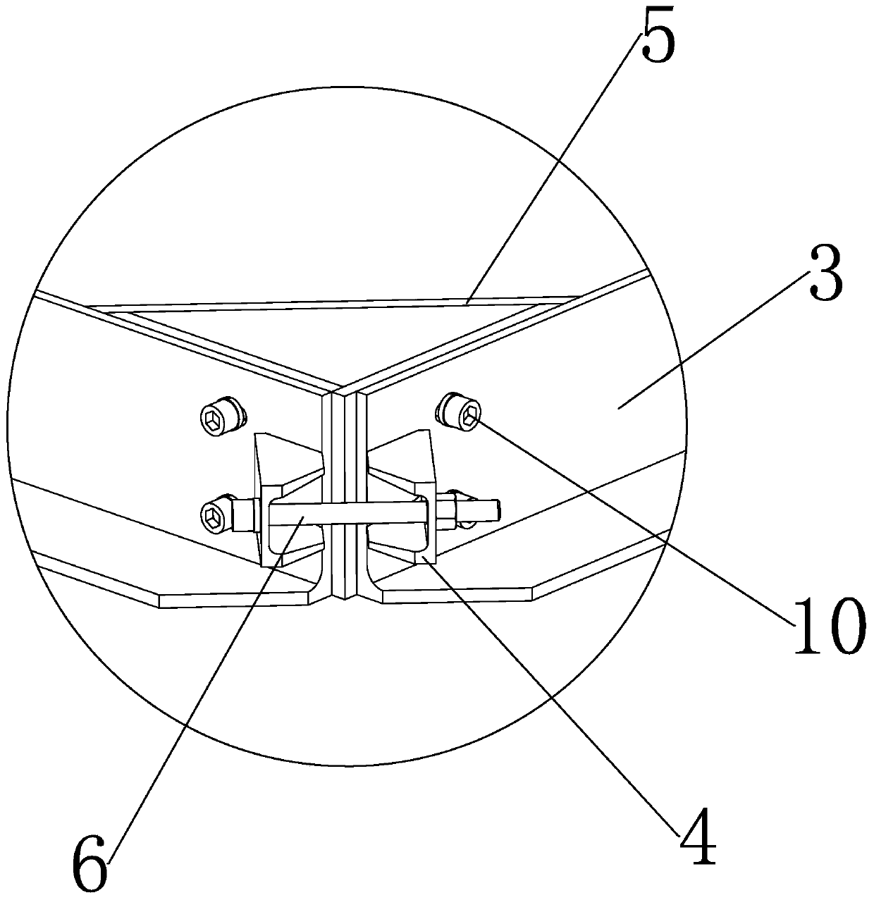
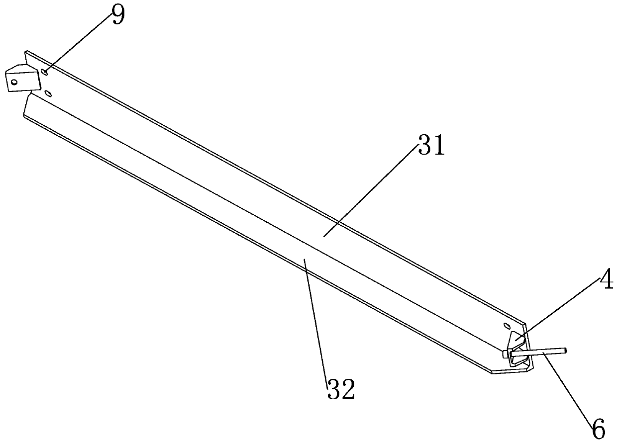
[0028] Such as Figure 1 to Figure 5 As shown, a sitting grouting mold for auxiliary prefabricated cover beam and prefabricated column connection is characterized in that it includes a sitting grouting frame 2 formed by splicing side molds 1 to accommodate the grouting slurry. The side molds include a body 3 and a Two connectors 4 are respectively arranged at both ends of the body in the length direction, and a slurry stopper 5 is provided at the corner of the sitting frame. Part and the first fixing part 6 cooperate to form a detachable connection; the section of the body is "L" shape, the body includes a first folded plate 31 and a second folded plate 32, the second folded plate includes a large end and a small end, The large end of the second folded plate is fixedly connected to the lower edge of the first folded plate, and the small end of the second folded plate arranged along the normal direction of the first folded plate is located outside the sitting frame; the stopper...


PUM


Abstract

The utility model discloses a bedding mortar mold for assisting connection of a prefabricated cover beam and a prefabricated stand column, and aims to solve the technical problem that in the prior art, in the connection process of the prefabricated stand column and the prefabricated cover beam, a bedding mortar mold with poor universality cannot be applied to the installation process of the prefabricated stand column and the prefabricated cover beam which are inconsistent in size, so that the waste rate of the bedding mortar mold is high. The bedding mortar mold comprises a bedding mortar frame which is formed by splicing side molds and used for containing bedding mortar. Each side mold comprises a body and two connecting pieces arranged at the two ends of the body in the length directionof the body respectively, mortar stopping pieces are arranged at the corners of the bedding frame and detachably connected with the inner side face of the bedding frame, and every two adjacent side molds are detachably connected through matching of the connecting pieces and the first fixing pieces.

Description

technical field [0001] The invention relates to the technical field of building construction, in particular to a sitting grout mold for assisting the connection of prefabricated cover beams and prefabricated columns. Background technique [0002] The cap beam refers to the beam set on the top of the bent pile pier in order to support, distribute and transmit the load of the superstructure, also known as the cap beam. Reinforced concrete or less-reinforced concrete beams are set on bridge piers (platforms) or row piles, and their main function is to support the upper structure of the bridge and transfer all loads to the lower structure. At present, in order to improve construction efficiency, the construction method of prefabricating columns and cover beams in factories and then assembling them on site is often used. [0003] The Chinese patent with the application number CN201910488278.0 discloses a prefabricated cover beam and construction method of an assembled bridge. A...

Claims


Application Information

Patent Timeline
IPC IPC(8): E01D21/00
CPCE01D21/00
Inventor 迟文明蒋锋潘森兵黄祎涵金一峰斯振兴
Owner 绍兴市城投建筑工业化制造有限公司
Why Eureka
Try Eureka