Straight pipe and clamp ring matching structure for swimming pool pump

A matching structure and clasp technology, applied in the direction of pipe supports, pipes/pipe joints/pipe fittings, mechanical equipment, etc., can solve the problems of high cost, time-consuming and laborious, and inability to disassemble the pipe, so as to ensure firmness and enhance the strength of the circumferential surface Effect

Pending Publication Date: 2020-05-19
巨龙电机(宁德)有限公司
View PDF0 Cites 0 Cited by
  • Summary
  • Abstract
  • Description
  • Claims
  • Application Information

AI Technical Summary

Problems solved by technology

The snap ring of the existing straight pipe of the swimming pool pump belongs to the integral casting structure. The integral casting snap ring meets the strength and installation requirements, but it cannot be disassembled from the pipe. If any supporting parts are damaged, the pipe must be sawn off and reinstalled. Installation and connection are not only time-consuming and labor-intensive, but also costly

Method used


Image

  • Straight pipe and clamp ring matching structure for swimming pool pump
  • Straight pipe and clamp ring matching structure for swimming pool pump
  • Straight pipe and clamp ring matching structure for swimming pool pump

Examples


Embodiment 1

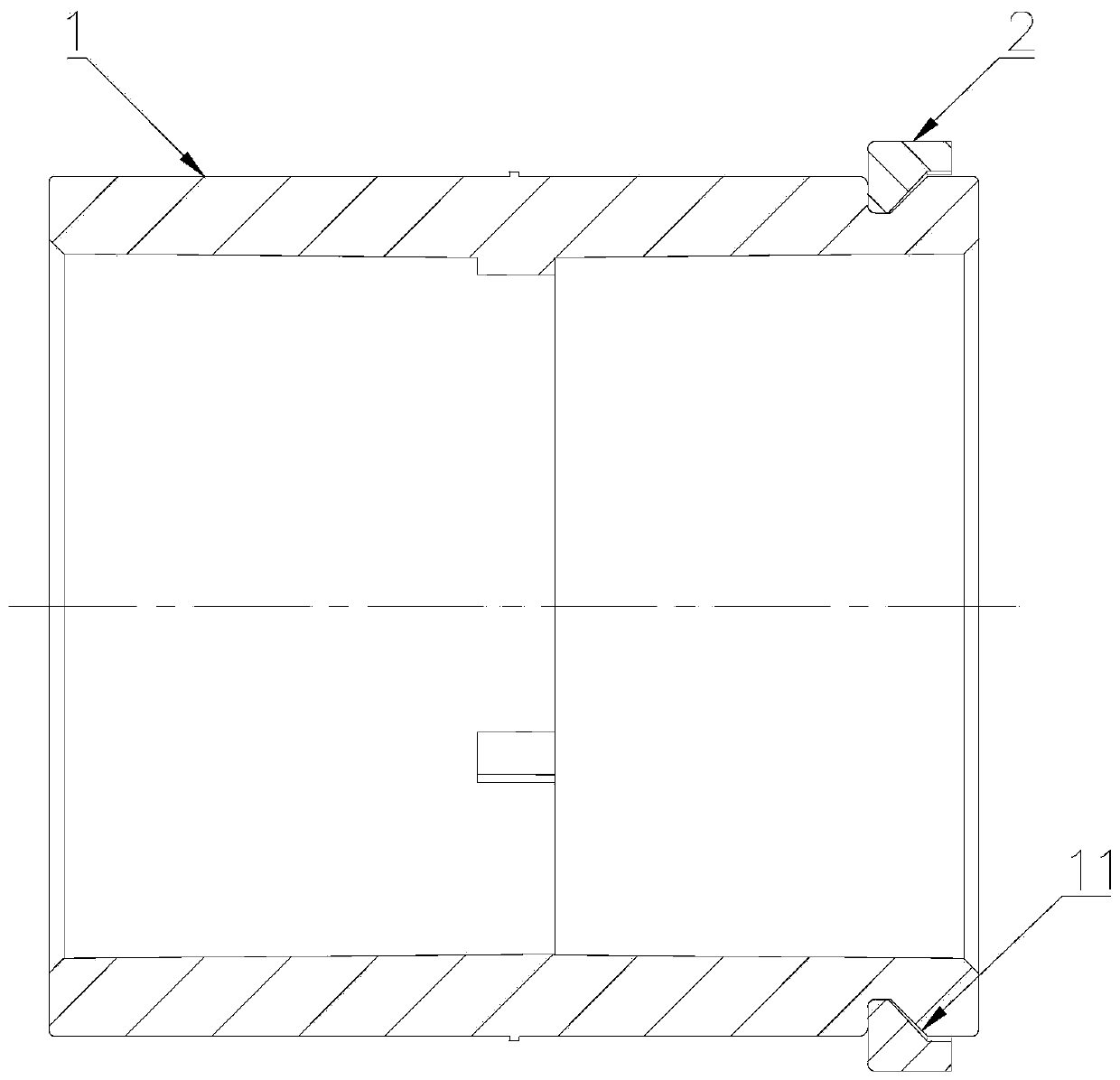
[0035] Please refer to Figure 1 to Figure 2 , Embodiment 1 of the present invention is: a straight pipe clasp fitting structure for a swimming pool pump, including a pipe main body and a clasp main body;

[0036] The main body of the pipe is cylindrical, the inside of the main body of the pipe is hollow and a through hole is opened in the axial direction, the outer wall of the main body of the pipe near the opening end is provided with an annular groove, the cross-sectional shape of the annular groove is a right-angled trapezoid, The hypotenuse of the right-angled trapezoid is located on the side of the annular groove close to the open end;

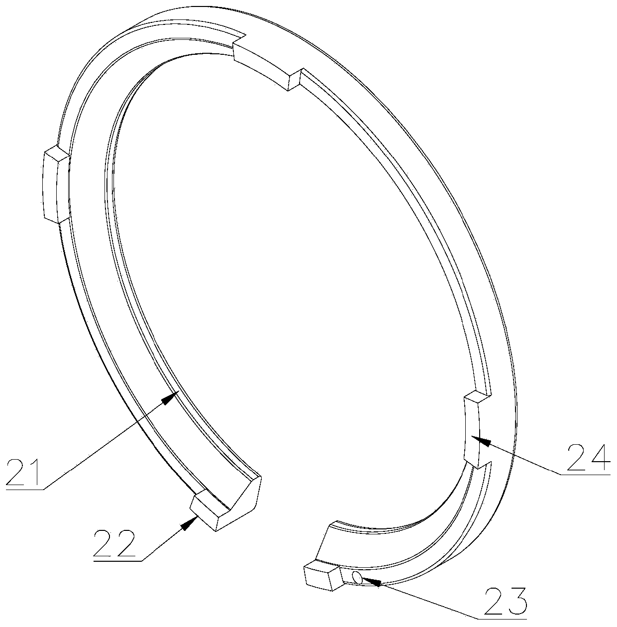
[0037] The main body of the snap ring has a ring structure, the main body of the snap ring has a fracture, and the inner wall of the main body of the snap ring is provided with an annular boss whose shape matches the annular groove.

Embodiment 2

[0038] Please refer to Figure 1 to Figure 2 , the second embodiment of the present invention is: a straight pipe clasp fitting structure for a swimming pool pump, including a pipe main body and a clasp main body;

[0039] The main body of the pipe is cylindrical, the inside of the main body of the pipe is hollow and a through hole is opened in the axial direction, the outer wall of the main body of the pipe near the opening end is provided with an annular groove, the cross-sectional shape of the annular groove is a right-angled trapezoid, The hypotenuse of the right-angled trapezoid is located on the side of the annular groove close to the open end;

[0040] The main body of the snap ring has a ring structure, the main body of the snap ring has a fracture, and the inner wall of the main body of the snap ring is provided with an annular boss whose shape matches the annular groove.

[0041] The snap ring main body is provided with fixing bosses on the end surface facing the op...


PUM


Abstract

The invention relates to the technical field of pump body equipment, in particular to a straight pipe and clamp ring matching structure for a swimming pool pump. The straight pipe and clamp ring matching structure comprises a pipeline body and a clamp ring body. The pipeline body is cylindrical. The pipeline body is internally hollow and is provided with a through hole in the axial direction. Theouter wall, close to the opening end, of the pipeline body is provided with a ring groove. The cross section of the ring groove is shaped like a right trapezoid. A bevel edge of the right trapezoid islocated on the side, close to the opening end, of the ring groove. The clamp ring body is of a ring structure. The clamp ring body is provided with a gap. The inner wall of the clamp ring body is provided with an annular boss matched with the ring groove in shape. Through the straight pipe and clamp ring matching structure, a detachable structure between the clamp ring body and the pipeline bodyis realized, and the strength and firmness of the matching structure of the clamp ring body and the pipeline body are ensured.

Description

technical field [0001] The invention relates to the technical field of pump body equipment, in particular to a snap ring matching structure for a straight pipe for a swimming pool pump. Background technique [0002] The swimming pool pump is a kind of horizontal direct-coupled centrifugal pump. Its motor has an extended shaft directly connected to the impeller and has a preset filter. It is used for water circulation in the swimming pool filtration system, pumping clean water or mild water with suspended particles Sewage pump body. The snap ring of the existing straight pipe of the swimming pool pump belongs to the integral casting structure. The integral casting snap ring meets the strength and installation requirements, but it cannot be disassembled from the pipe. If any supporting parts are damaged, the pipe must be sawn off and reinstalled. Installation and connection are not only time-consuming and labor-intensive, but also costly. Contents of the invention [0003]...

Claims


Application Information

Patent Timeline
Patent Type & Authority Applications(China)
IPC IPC(8): F16L3/12
CPCF16L3/12
Inventor 周国辉薛茂刘淑青李政博白淳鑫蔡锦峰
Owner 巨龙电机(宁德)有限公司
Why Eureka
Try Eureka