Coal powder distributor for coal-fired blast furnace

A distributor, blast furnace technology, applied in the direction of block/powder supply/distribution, combustion method, combustion equipment, etc., can solve the problem of inability to distinguish between over-rich combustion and under-lean combustion, increase incomplete combustion of pulverized coal, and thermal efficiency of boiler units It can reduce the operation cost of blast furnace, reduce the cost of flue gas treatment and improve the efficiency.

Active Publication Date: 2021-09-17
山西晋钢智造科技实业有限公司
View PDF0 Cites 0 Cited by
  • Summary
  • Abstract
  • Description
  • Claims
  • Application Information

AI Technical Summary

Problems solved by technology

[0003] At present, during the operation of the coal-fired blast furnace, the pulverized coal enters the boiler through the burner with the primary air for combustion, but there is a certain speed difference between the wind and the pulverized coal during the transportation process, so that the concentration Decrease, so that the concentration of pulverized coal that enters the boiler through the burner after distribution is lower than the optimal ignition concentration, especially for low-volatility coal, in order to reduce the heat of ignition, the concentration of pulverized coal transported is often increased by reducing the primary air rate, but it is too low The wind speed is easy to cause the pulverized coal to accumulate in the pipeline, resulting in a blockage of the primary air duct, so the wind speed has to be increased, which makes it difficult to catch fire. At the same time, the traditional pulverized coal distributor distributes the pulverized coal evenly into the boiler, and cannot distinguish The over-rich combustion and over-lean combustion make the incomplete combustion of pulverized coal, resulting in NO X Emissions increase, and the loss of incomplete combustion of pulverized coal increases, reducing the thermal efficiency of the boiler unit

Method used


Image

  • Coal powder distributor for coal-fired blast furnace
  • Coal powder distributor for coal-fired blast furnace
  • Coal powder distributor for coal-fired blast furnace

Examples


Embodiment Construction

[0021] The following will clearly and completely describe the technical solutions in the embodiments of the present invention with reference to the accompanying drawings in the embodiments of the present invention. Obviously, the described embodiments are only some, not all, embodiments of the present invention. Based on the embodiments of the present invention, all other embodiments obtained by persons of ordinary skill in the art without making creative efforts belong to the protection scope of the present invention.

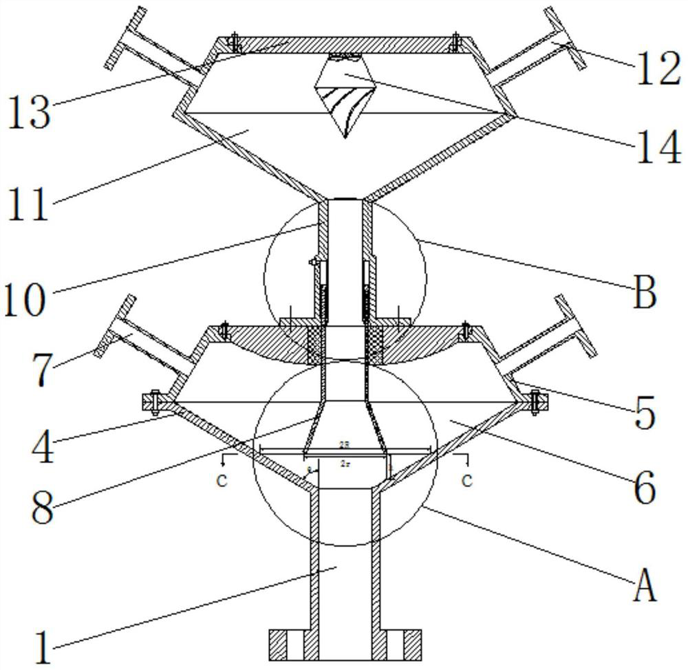
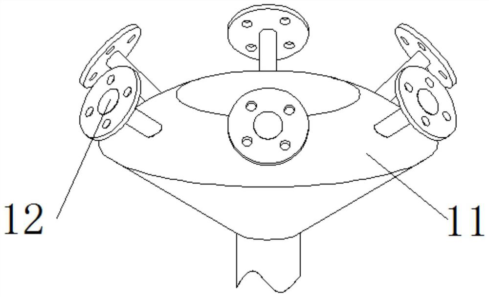
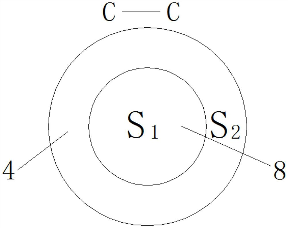
[0022] see Figure 1-6 , a pulverized coal distributor for a coal-fired blast furnace, comprising an air inlet main pipe 1, a bottom italic body 4 is fixedly installed on the top of the air inlet main pipe 1, and an upper cover 5 is fixedly installed on the top of the bottom italic body 4 by bolts, and the upper cover 5 The first distribution duct 7 is evenly and fixedly installed on the side of the upper cover 5, and the top center of the upper cover 5 is mov...


PUM


Abstract

The invention relates to the technical field of coal-fired blast furnaces, and discloses a pulverized coal distributor for a coal-fired blast furnace. The upper cover is installed. Through the arrangement of the first distribution chamber, the movable standpipe and the second distribution chamber, the primary air entering from the air inlet main pipe and the pulverized coal carried by it are divided into two parts with different concentrations, so as to realize the separation of the concentration of the pulverized coal, and then The first distribution chamber and the second distribution chamber are evenly distributed and then transferred from the first distribution air duct and the second distribution air duct to the boiler respectively. Concentration of pulverized coal is ignited to improve the low-load and warm combustion capacity of combustion, and at the same time, it can achieve stable ignition of inferior coal, improve combustion efficiency, reduce blast furnace operating costs, and improve the utilization rate of inferior coal.

Description

technical field [0001] The invention relates to the technical field of coal-fired blast furnaces, in particular to a pulverized coal distributor for coal-fired blast furnaces. θ Background technique [0002] The pulverized coal distributor refers to the device that evenly distributes the primary air and pulverized coal to the subsequent primary air ducts in the direct-blowing pulverizing system. Figure 7 , the mixture of wind and pulverized coal enters the distribution box 2 from the air inlet main pipe 1, and then spreads evenly in the distribution box 2, and then is transported to the burner through the primary air pipe 3, and is ignited in the boiler, but the pulverized coal distribution There are certain deficiencies in the use of the device, as follows: [0003] At present, during the operation of the coal-fired blast furnace, the pulverized coal enters the boiler through the burner with the primary air for combustion, but there is a certain speed difference between t...

Claims


Application Information

Patent Timeline
Patent Type & Authority Patents(China)
IPC IPC(8): F23K3/02
CPCF23K3/02F23K2203/006F23K2203/008F23K2203/201
Inventor 周德军
Owner 山西晋钢智造科技实业有限公司
Why Eureka
Try Eureka