Fuel cell cathode side humidity adjustment control system and method

A fuel cell cathode and humidity adjustment technology, which is applied in the direction of fuel cell control, fuel cells, fuel cell additives, etc., can solve the problems of fuel cell loss, untimely adjustment, battery external equipment to reduce battery load, etc., to reduce loss, The effect of improving detection accuracy and improving work efficiency

Active Publication Date: 2020-05-19
浙江高成绿能科技有限公司
View PDF5 Cites 6 Cited by
  • Summary
  • Abstract
  • Description
  • Claims
  • Application Information

AI Technical Summary

Problems solved by technology

[0007] But this type of patent has the following problems. 1. Since the relative humidity of the air at the cathode of the fuel cell changes dynamically, if the water vapor content in the air exceeds 30%, it will be converted into liquid water in large quantities.
At the same time, because the air in the fuel cell flows rapidly and the water vapor contained in it changes dynamically, the water sensor can only roughly measure the relative humidity of the air in the designated space along with the flow of air, so there is generally a certain delay, and then it may It will not be adjusted in time when the dry film of the battery stack or the water blockage is serious, which will cause partial loss of the fuel cell
2. When water blocking occurs, it is necessary to reduce the load of the battery to avoid battery loss, but most of the existing patents cannot use intelligent adjustment to forcefully control the external equipment of the battery to reduce the battery load

Method used


Image

  • Fuel cell cathode side humidity adjustment control system and method
  • Fuel cell cathode side humidity adjustment control system and method
  • Fuel cell cathode side humidity adjustment control system and method

Examples


Embodiment 1

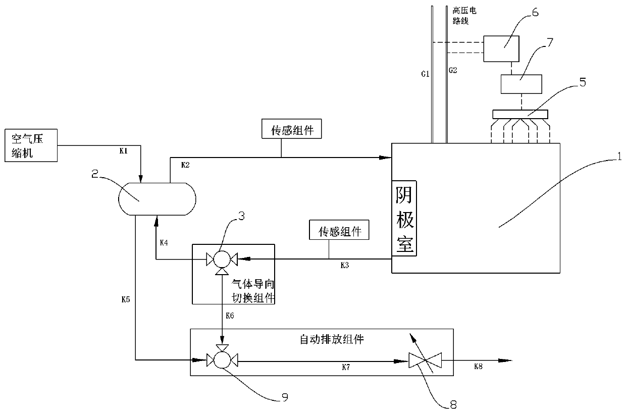
[0045] Such as figure 1 As shown, this embodiment provides a specific usage method including steps ① to ⑥.

[0046] ①Reference Figure 1 , the low-temperature dry air enters the humidifier 2 through the air duct K1 after being pressurized by the air compressor.

[0047] ②The high temperature and humid air in the cathode chamber of the cathode side of the fuel cell stack 1 enters the humidifier 2 through the air pipeline K3, the first electromagnetic three-way valve 3 and the air pipeline K4. At this time, the section of the air pipeline K3 to K4 is unblocked, and the air pipeline K3 to K6 Road segment closed.

[0048] ③The temperature and humidity exchange between low-temperature dry air and high-temperature humid air is completed in the humidifier 2. The temperature and humidity of the original low-temperature dry air rise and enter the fuel cell stack 1 through the air duct K2. The temperature and humidity of the original high-temperature humid air After being lowered, th...

Embodiment 2

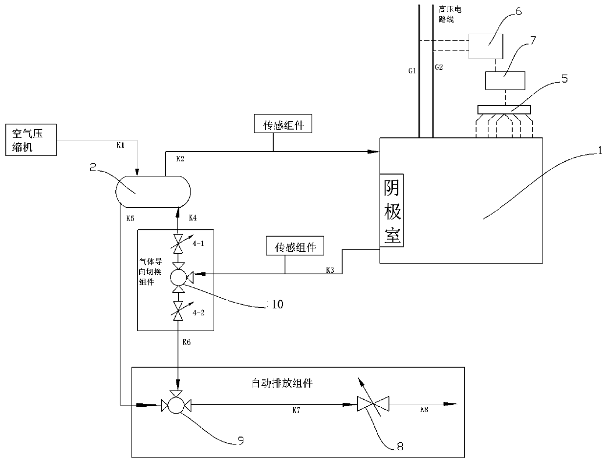
[0055] Such as figure 2 As shown, the general use steps of embodiment 2 are similar to those of embodiment 1, except that the system of embodiment 2 is provided with a first throttle valve 4-1 and a second damper 4-1 on the air pipe connected to the humidifier 2 and the automatic discharge assembly respectively. The throttle valve 4-2 replaces the first electromagnetic three-way valve 3 with the normally open first pilot three-way valve 10 simultaneously. Among them, the first throttle valve 4-1 and the second throttle valve 4-2 are logically interlocked, and if any one is opened, the other one must be closed; in addition, for the convenience of control, the throttle valve states are only open and closed, and there is no The intermediate state of the opening.


PUM


Abstract

The invention provides a fuel cell cathode side humidity adjustment control system and method. The relative humidity condition of the cathode of the cell stack is rapidly and accurately obtained through the voltage change rule of the fuel cell, and compared with an existing humidity sensor feedback control method, the method is higher in control sensitivity and is remarkably improved in detectionaccuracy, and can reduce the loss of the fuel cell caused by dry film and water plugging phenomena. According to the invention, the water vapor content at the cathode of the fuel cell can be controlled within a certain range, so that the working efficiency of the fuel cell is improved. According to the invention, a gas guiding and switching assembly is used for intelligently adjusting the communication relationship between a low-position connection port of a cathode chamber of the cell stack and an automatic discharge assembly and a humidifier, so that air with high air relative humidity can be fed into a cathode chamber through a high-position connecting port by matching with the humidifier, and the working efficiency of the fuel cell is improved by properly improving the water vapor content of the cathode chamber.

Description

technical field [0001] The invention relates to a fuel cell control system, in particular to a fuel cell cathode side humidity adjustment control system and method. Background technique [0002] With the rapid development of science and technology, the development direction of automobiles has gradually shifted from traditional fuel engine-driven vehicles to electric-driven vehicles. As an energy supply device for various vehicles, fuel cell systems can provide electric energy for vehicles. Its power generation can not only directly drive the motor to do work, but also charge the power battery. [0003] In addition, the fuel cell system can also become a stationary power generation device. Chemical plants, power plants, and iron and steel plants generally produce waste hydrogen. According to the amount of waste hydrogen purified, fuel cell power stations ranging from hundreds of kilowatts to megawatts can be built, which can generate economic value and comprehensively treat ...

Claims


Application Information

Patent Timeline
Patent Type & Authority Applications(China)
IPC IPC(8): H01M8/04119H01M8/04492H01M8/04828
CPCH01M8/04126H01M8/04492H01M8/045H01M8/04828Y02E60/50
Inventor 袁飞张晨曹立权
Owner 浙江高成绿能科技有限公司
Why Eureka
Try Eureka