Filter and communication equipment
A filter and integrated technology, applied in the field of communication, can solve the problems of structural limitation and material cost increase, and achieve the effect of cost reduction, cost reduction, and convenient capacitive cross-coupling
- Summary
- Abstract
- Description
- Claims
- Application Information
AI Technical Summary
Problems solved by technology
Method used
Image
Examples
Embodiment 1
[0037] Such as Figure 4 As shown, a filter disclosed in Embodiment 1 of the present invention includes a cavity 301, a cover plate 302, a resonance post 303 and a tuning screw 304, wherein the cover plate 302 is arranged on the cavity 301 to form a closed resonant For the cavity 305 , during implementation, the cover plate 302 can be integrally formed with the cavity 301 , and can also be fixed to the cavity 301 by fastening screws or other fixing structures.
[0038] The resonant column 303 is disposed in the resonant cavity 305 , and is integrally formed with the bottom surface of the cavity 301 . In the first embodiment, the resonant column 303 is integrally formed on the bottom of the cavity 301 and is perpendicular to the bottom of the cavity 301 , and its top is close to the bottom of the cover 302 but not in contact with the bottom of the cover 302 . The integrally formed resonant column 303 structure can be integrally formed by die-casting, which saves processing mat...
Embodiment 2
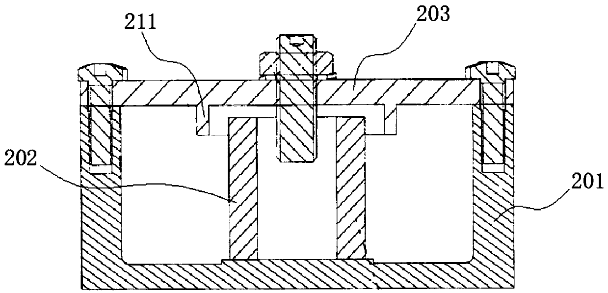
[0046] combine Figure 5 and Figure 6 As shown, a filter disclosed in Embodiment 2 of the present invention includes a cavity 401, a cover plate 402, a resonant column and a tuning screw 404, wherein the cover plate 402 is arranged on the cavity 401 to form a closed resonant cavity 405. During implementation, the cover plate 402 can be integrally formed with the cavity body 401, or can be fixed to the cavity body 401 by fastening screws or other fixing structures.
[0047] combine Figure 7 ~ Figure 9 As shown, the resonant column is arranged in the resonant cavity 405. The difference from the structure of the above-mentioned embodiment 1 is that in this embodiment 2, the resonant column is separately arranged in the resonant cavity 405, which specifically includes the split upper resonant column 403 and The lower resonant column 409, the lower resonant column 409 is integrally formed by the central part of the bottom surface of the resonant cavity 405 protruding upwards, t...
Embodiment 3
[0056] A communication device disclosed in Embodiment 3 of the present invention includes the filter described in Embodiment 1 or 2 above.
[0057] In the filter and communication equipment provided by the embodiment of the present invention, by improving the structure of the traditional tuning screw extending into the resonant column, the middle part of the tuning screw is hollowed out to form a hollow part, and the resonant column protrudes to form a protrusion that matches the hollow part The upper end of the raised part extends into the hollow part, which increases the induction area between the tuning screw and the resonant column, which is equivalent to increasing the distributed capacitance of the resonator. On the one hand, it can achieve the purpose of low frequency. The structure of the body will not cause all the distributed capacitance to be concentrated in a closed space, which is convenient for reference electrical coupling, and will not affect the diffused distri...
PUM
 Abstract
Description
Claims
Application Information
 - R&D
- Intellectual Property
- Life Sciences
- Materials
- Tech Scout
- Unparalleled Data Quality
- Higher Quality Content
- 60% Fewer Hallucinations
Browse by: Latest US Patents, China's latest patents, Technical Efficacy Thesaurus, Application Domain, Technology Topic, Popular Technical Reports.
© 2025 PatSnap. All rights reserved.Legal|Privacy policy|Modern Slavery Act Transparency Statement|Sitemap|About US| Contact US: help@patsnap.com


