Antenna and multiple input multiple output (MIMO) antenna with same

An antenna and feeder technology, applied in the field of MIMO antennas, can solve the problems of increasing the area of ​​the radio frequency system, difficult to meet the system design requirements of low power consumption, and increasing the design of the electronic system feeder, so as to achieve strong anti-interference ability and high isolation. , to meet the effect of small volume

Active Publication Date: 2015-05-27
KUANG CHI INST OF ADVANCED TECH
View PDF5 Cites 0 Cited by
  • Summary
  • Abstract
  • Description
  • Claims
  • Application Information

AI Technical Summary

Problems solved by technology

However, the impedance matching network additionally increases the feeder design of the electronic system and increases the area of ​​the radio frequency system. At the same time, the matching network also introduces a lot of energy loss, which is difficult to meet the system design requirements of low power consumption.

Method used


Image

  • Antenna and multiple input multiple output (MIMO) antenna with same
  • Antenna and multiple input multiple output (MIMO) antenna with same
  • Antenna and multiple input multiple output (MIMO) antenna with same

Examples


Embodiment Construction

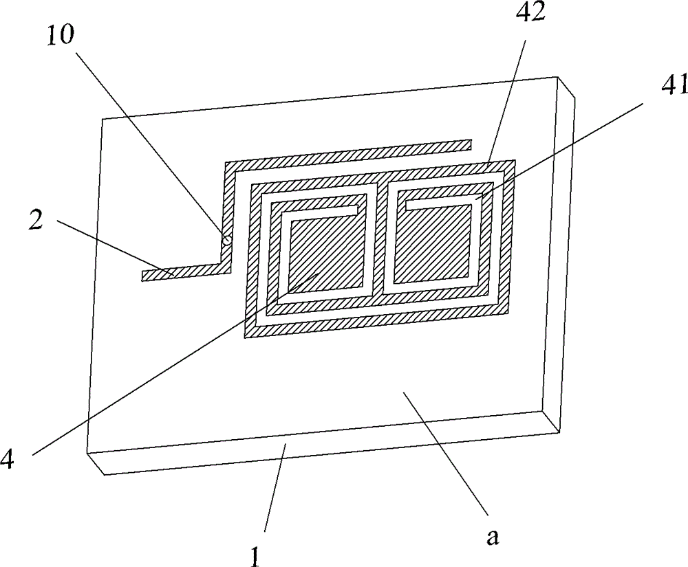
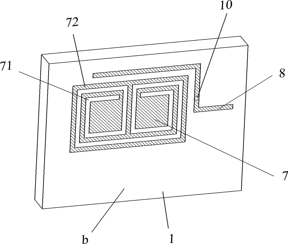
[0031] Such as Figure 1 to Figure 3 As shown, the antenna 100 of the present invention includes a first dielectric substrate 1, a first metal sheet 4 and a second metal sheet 7 attached to two opposite surfaces of the first dielectric substrate 1, and a first metal sheet 4 is provided around the first metal sheet 4. The feeder line 2 is provided with a second feeder line 8 surrounding the second metal sheet 7. The first feeder line 2 and the second feeder line 8 are respectively fed into the first metal sheet 4 and the second metal sheet 7 through a coupling manner. The first metal sheet 4 is hollowed out with a first micro-groove structure 41 to form a first metal trace 42 on the first metal sheet, and the second metal sheet 7 is hollowed out with a second micro-groove structure 71 to be on the second metal sheet. A second metal trace 72 is formed, and the first feed line 2 is electrically connected to the second feed line 8. This design is equivalent to increasing the physic...


PUM


Abstract

The invention relates to an antenna, which comprises a first dielectric substrate, a first metal sheet and a second metal sheet. The first and second metal sheets are attached to the two opposite surfaces of the first dielectric substrate. A first feeder line is arranged in a way of enclosing the first metal sheet. A second feeder line is arranged in a way of enclosing the second metal sheet. The first and second feeder lines feed signals in the first and second metal sheets in a coupling way respectively. A first micro-channel structure is hollowed in the first metal sheet to form first metal wiring on the first metal sheet. A second micro-channel structure is hollowed in the second metal sheet to form second metal wiring on the second metal sheet. The first and second feeder lines are electrically connected. A second dielectric substrate also covers the first metal sheet. According to the antenna, the metal sheets are arranged on the two surfaces of the first dielectric substrate, so that the area of the antenna is fully utilized, the antenna can work at low working frequency in such an environment, and the requirements of miniaturization, low working frequency and broadband multimode for the antenna are met. In addition, the invention also relates to a multiple input multiple output (MIMO) antenna with a plurality of antennae.

Description

Technical field [0001] The present invention belongs to the field of communications, and specifically relates to an antenna and a MIMO antenna with the antenna. Background technique [0002] With the rapid development of semiconductor technology, higher and higher requirements are put forward for the integration of today's electronic systems, and the miniaturization of devices has become a technical issue of great concern to the entire industry. However, unlike the development of IC chips that follow "Moore's Law", as another important component of electronic systems-radio frequency modules, they face the difficult technical challenge of device miniaturization. The radio frequency module mainly includes the main components such as mixing, power amplifier, filtering, radio frequency signal transmission, matching network and antenna. Among them, the antenna is used as the radiating unit and receiving device of the final radio frequency signal, and its working characteristics will ...

Claims


Application Information

Patent Timeline
Patent Type & Authority Patents(China)
IPC IPC(8): H01Q1/38H01Q21/00
Inventor 刘若鹏徐冠雄杨松涛
Owner KUANG CHI INST OF ADVANCED TECH
Why Eureka
Try Eureka