
Permanent magnet synchronous motor stator core

A permanent magnet synchronous motor and stator core technology, applied to synchronous motors with stationary armatures and rotating magnets, electrical components, electromechanical devices, etc., can solve problems such as high production costs, low speed, and affecting motor speed. To achieve the effect of reasonable structure and convenient use

Inactive Publication Date: 2020-05-19
河南全新机电设备有限公司
View PDF0 Cites 0 Cited by
  • Summary
  • Abstract
  • Description
  • Claims
  • Application Information

AI Technical Summary

Problems solved by technology

[0002] The ball mill is the key equipment for crushing the material after it is crushed. It is mainly used in cement, new building materials, refractory materials and other industries. At present, some direct drive motors of ball ink machines need low speed, and the number of poles of the motor directly affects the speed of the motor. Existing motors have complex structures and high production costs in order to achieve a large number of poles

Method used


Image

  • Permanent magnet synchronous motor stator core
  • Permanent magnet synchronous motor stator core

Examples


Embodiment Construction

[0012] In describing the present invention, it should be understood that the terms "longitudinal", "transverse", "upper", "lower", "front", "rear", "left", "right", "vertical", The orientations or positional relationships indicated by "horizontal", "top", "bottom", "inner", "outer", etc. are based on the orientations or positional relationships shown in the drawings, and are only for the convenience of describing the present invention, rather than indicating or It should not be construed as limiting the invention by implying that a referenced device or element must have a particular orientation, be constructed, and operate in a particular orientation.

[0013] The technical scheme of the present invention is described in detail in conjunction with the accompanying drawings,

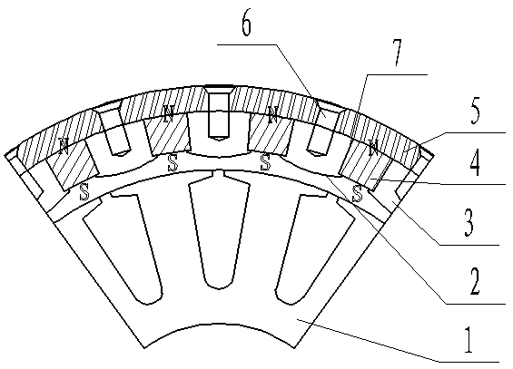
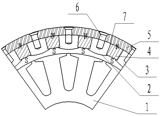
[0014] A permanent magnet synchronous motor stator core, including a stator mechanism 2 and a rotor mechanism 1, the stator mechanism is installed outside the rotor rotor mechanism, coil windings are arra...


PUM


Abstract

The invention discloses a permanent magnet synchronous motorstator core. The stator corecomprises a stator mechanism and a rotor mechanism. A shell sleevesan outer portion of an iron core; the shellisconnected with the iron core through a screw; permanent magnets are arranged in gaps among the iron cores; the adjacent permanent magnets have the same magnetism; baffles are arranged at two ends ofthe permanent magnet; and each baffle is fixedly connected with the iron core.In the invention, a center height of the shellmade of magnetism isolating metal and the center height of a low-speed large-torque motor with the same power are obviously reduced; and adiameter of the permanent magnet synchronous motor is reduced, the magnetism of the adjacent permanent magnets is set to be the same, thenumber of poles of the motor is doubled under acondition that the same number of permanent magnets are used, and the motor can rotate at a lower speed under the condition that the number of the permanent magnets is the same as that of the existing permanent magnets.

Description

technical field [0001] The invention relates to the technical field of motors, in particular to a stator core of a permanent magnet synchronous motor. Background technique [0002] The ball mill is the key equipment for crushing the material after it is crushed. It is mainly used in cement, new building materials, refractory materials and other industries. At present, some direct drive motors of ball ink machines need low speed, and the number of poles of the motor directly affects the speed of the motor. The existing motor has a complex structure in order to achieve a large number of poles, and the production cost is relatively high. Contents of the invention [0003] The technical problem to be solved by the present invention is to provide a permanent magnet synchronous motor stator core with a simple structure, which can reduce the usage of permanent magnets and save costs. [0004] In order to achieve the above objectives, the technical solution of the present inventi...

Claims


Application Information

Patent Timeline
Patent Type & Authority Applications(China)
IPC IPC(8): H02K1/17H02K1/18H02K21/14H02K5/06
CPCH02K1/17H02K1/18H02K5/06H02K21/14
Inventor 尚勤贵
Owner 河南全新机电设备有限公司
Learn More