Method for realizing remote operation of motor start and stop and state display through CAN bus

A CAN bus, remote operation technology, applied in the field of electronics, can solve the problems of inconvenient operation, many wiring, long cable distance, etc., to reduce the effect of on-site wiring

Pending Publication Date: 2020-05-19
许昌中科森尼瑞技术有限公司
View PDF0 Cites 0 Cited by
  • Summary
  • Abstract
  • Description
  • Claims
  • Application Information

AI Technical Summary

Problems solved by technology

[0003] The traditional solution requires more wiring (theoretically requires 5 wires), and uses a po

Method used


Image

  • Method for realizing remote operation of motor start and stop and state display through CAN bus
  • Method for realizing remote operation of motor start and stop and state display through CAN bus
  • Method for realizing remote operation of motor start and stop and state display through CAN bus

Examples


Embodiment Construction

[0035] The technical solutions in the embodiments of the present invention will be clearly and completely described below in conjunction with the accompanying drawings in the embodiments of the present invention. Obviously, the described embodiments are only part of the embodiments of the present invention, not all of them. Based on the embodiments of the present invention, all other embodiments obtained by persons of ordinary skill in the art without making creative efforts belong to the protection scope of the present invention.

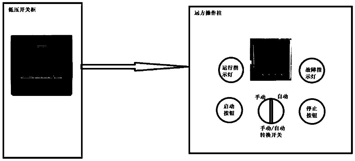
[0036] see figure 1 , is the system diagram of the remote control display unit of the operation column. The system is equipped with a low-voltage switch cabinet motor protector, which is connected with the remote control display unit of the operation column through a CAN communication line to realize remote operation control and display.

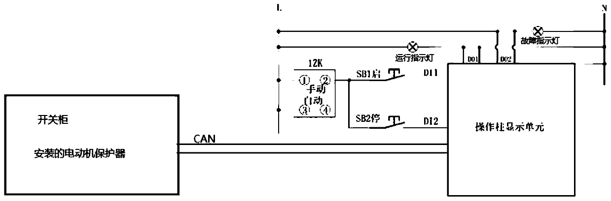
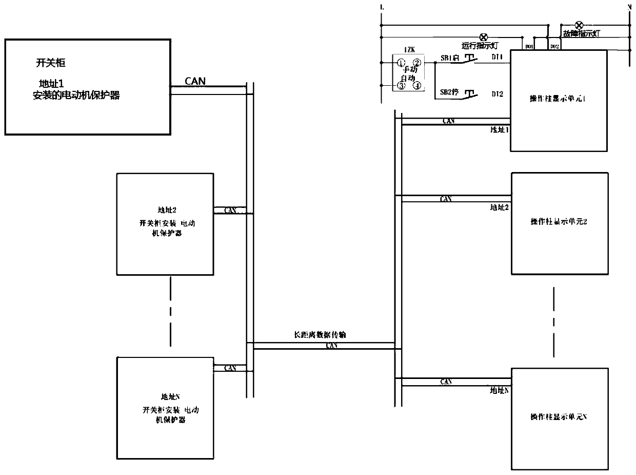
[0037] see figure 2 , is the secondary wiring diagram of the remote control display unit of the operation co...


PUM


Abstract

The invention provides a method for realizing remote operation of motor start and stop and state display through a CAN bus. The method is characterized in that the method comprises the following steps: 1, a plurality of operation column remote control display units and a plurality of motor protectors in a switch cabinet are connected through one CAN bus; 2, communication parameters of the CAN busare set; 3, the operation column remote control display units on operation columns control a motor to start and stop; and 4, the operation column remote control display units monitor the operating state of the motor. According to the method, only one twisted-pair communication line (2) is needed on site, and if the distance between the plurality of operation columns is short, the plurality of operation columns can share one communication line, so that the on-site wiring is greatly reduced.

Description

technical field [0001] The invention relates to the field of electronic technology, in particular to a method for realizing remote operation of motor start-stop and state display through CAN bus. Background technique [0002] In the process of industrial field use, the motor protection controller is generally installed in the power distribution cabinet, and the power distribution cabinet is installed in one place. The motor installation position is generally several hundred meters away from the power distribution cabinet, and the operation column display control unit is installed next to the motor. , On-site staff use the operation column to start and stop the motor, monitor the working state of the motor, and the working current of the motor. The traditional scheme uses hard-wiring mode, pulls 5 control wires over a long distance, and operates the column control button in series with the contactor circuit. At least 3 control wires (start, stop and common terminal) are requi...

Claims


Application Information

Patent Timeline
IPC IPC(8): H02P5/74G05B23/02
CPCG05B23/0213G05B2219/24065H02P5/74
Inventor 陈春华王志伟唐文正张文萍蔡元博袁彩蝶刘增辉王世杰马东祥陈西洋李东东
Owner 许昌中科森尼瑞技术有限公司
Why Eureka
Try Eureka