
Chip and capacitive isolation circuit

An isolated circuit and capacitive technology, applied in the direction of logic circuit interface device, logic circuit connection/interface layout, etc., can solve the problem of high circuit cost, achieve strong suppression ability, reduce circuit cost, and reduce the number of effects

Pending Publication Date: 2020-05-19
3PEAK INC
View PDF6 Cites 3 Cited by
  • Summary
  • Abstract
  • Description
  • Claims
  • Application Information

AI Technical Summary

Problems solved by technology

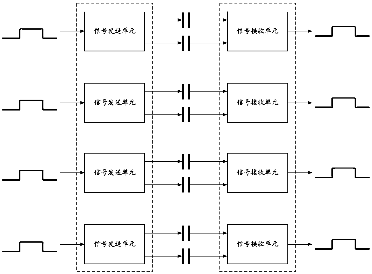
[0014] Each signal path requires a pair of independent isolation capacitors, such as image 3 As shown, when there are 4 signal paths, 8 independent isolation capacitors are required, and the circuit cost is obviously higher

Method used


Image

  • Chip and capacitive isolation circuit
  • Chip and capacitive isolation circuit
  • Chip and capacitive isolation circuit

Examples


Embodiment Construction

[0054] The present invention will be described in detail below in conjunction with various embodiments shown in the drawings. However, these embodiments do not limit the present invention, and structural, method, or functional changes made by those skilled in the art according to these embodiments are included in the protection scope of the present invention.

[0055] The invention discloses a chip. The chip includes several signal sending units and / or signal receiving units, and several clock generating units and / or clock receiving units. The channel, the clock generating unit and the clock receiving unit are used to generate or receive clock signals to modulate or demodulate signals transmitted in the signal channel.

[0056] The invention also discloses a capacitive isolation circuit, comprising:

[0057] The first chip includes several signal sending units and / or signal receiving units, and several clock generating units and / or clock receiving units;

[0058] The second ...


PUM


Abstract

The invention discloses a chip and a capacitive isolation circuit. The isolation circuit comprises a first chip which comprises a plurality of signal transmitting units and / or signal receiving units,and a plurality of clock generating units and / or clock receiving units; a second chip which comprises a plurality of signal receiving units and / or signal transmitting units and a plurality of clock receiving units and / or clock generating units; and a plurality of isolation capacitors positioned between the signal transmitting units and the signal receiving units of the first chip and the second chip and between the clock generating unit and the clock receiving unit of the first chip and the second chip. The clock generating units and the clock receiving units are used for generating or receiving clock signals so as to modulate or demodulate signals transmitted in signal paths of the first chip and the second chip. According to the invention, the clock is adopted to modulate the signal, and the signal transmitted between chips is the modulation signal, so that the common-mode disturbance suppression capability is relatively strong; according to the invention, the number of isolation capacitors is reduced, and the circuit cost is greatly reduced.

Description

technical field [0001] The invention belongs to the technical field of isolation circuits, and in particular relates to a chip and a capacitive isolation circuit. Background technique [0002] The isolation circuit is used for signal transmission between two circuits. The two circuits are in different voltage domains, and the voltage difference between the two circuits can reach several thousand volts, so there cannot be a DC path between them. Capacitors are widely used to isolate DC signals and allow AC signals to pass through, so capacitive isolation circuits are an important implementation method of isolation circuits. But if the voltage that needs to be isolated is very high, such as several thousand volts, then the production cost of the isolation capacitor is very high, accounting for the main cost of the entire circuit. [0003] ginseng figure 1 Shown is a schematic diagram of a capacitive isolation circuit in the prior art, which includes a signal sending unit 11'...

Claims


Application Information

Patent Timeline
IPC IPC(8): H03K19/0175
CPCH03K19/017509
Inventor 应峰
Owner 3PEAK INC
Learn More