Electrical equipment automation control cabinet
A technology of electrical equipment and control cabinets, which is applied in the field of control cabinets, can solve problems such as burnout of electrical components, affecting circuits, and fire of electrical components, and achieve the effects of avoiding losses and improving the sealing and stability of connections
- Summary
- Abstract
- Description
- Claims
- Application Information
AI Technical Summary
Problems solved by technology
Method used
Image
Examples
Embodiment 1
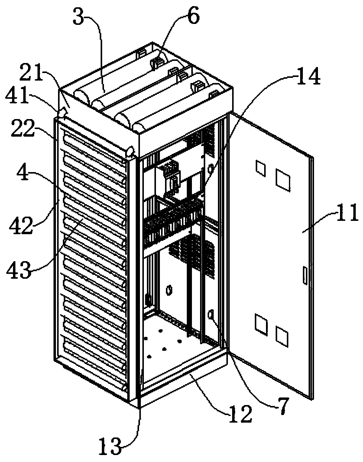
[0044] Such as Figure 1-Figure 7 As shown, the sealing mechanism 5 includes a fixed joint 51, a first connecting head 52, a sealing ring 53, and a thimble 54. The fixed joint 51 is connected to the connecting elbow 41 of the transmission mechanism 4 through threads, and the air inlet end of the fixed joint 51 is provided with a first connection. Head 52, the inner side of the first connecting head 52 is provided with a thimble 54, the air inlet end of the fixed joint 51 is connected to the first tank connecting head 55, there is only a sealing ring 53 between the first connecting head 52 and the first tank connecting head 55, The first tank connector 55 is arranged on the feeding mechanism 3, the other end of the feeding mechanism 3 is connected with a fixed tapered block 56, and the fixed tapered block 56 is connected on the fixed seat 59, and one end of the fixed tapered block 56 and the pre-tightening cone Shaped block 57 is connected, and the upper end of pretightening co...
Embodiment 2
[0047] The difference between this embodiment and Embodiment 1 is that the sealing mechanism 5 includes a fixed joint 51, a sealing ring 53, a thimble 54, and a second connector 511. One end of the fixed joint 51 is connected to the second connector 511 by welding, and the second connector 511 The inside is provided with a thimble 54, and a sealing ring 53 is provided between the fixed joint 51 and the second connection head 511. The second connection head 511 is threaded to the second tank body connection head 512 on the feeding mechanism 3. When it is necessary to install liquid nitrogen When the tank 31 and the gas fire extinguisher 32 are used, the second tank connector 512 on the liquid nitrogen tank 31 is threaded and matched with the second connector 511, so that when the valve body inside the second connector 511 contacts the thimble 54, the The liquid nitrogen tank 31 is connected with the fixed joint 51.
PUM
 Abstract
Description
Claims
Application Information
 - R&D
- Intellectual Property
- Life Sciences
- Materials
- Tech Scout
- Unparalleled Data Quality
- Higher Quality Content
- 60% Fewer Hallucinations
Browse by: Latest US Patents, China's latest patents, Technical Efficacy Thesaurus, Application Domain, Technology Topic, Popular Technical Reports.
© 2025 PatSnap. All rights reserved.Legal|Privacy policy|Modern Slavery Act Transparency Statement|Sitemap|About US| Contact US: help@patsnap.com


