Device for detecting abnormality in attachment of tool

A cutting tool and abnormal technology, applied in positioning devices, manufacturing tools, measuring/indicating equipment, etc., can solve problems such as difficulty in detecting the abnormal state of tool installation and inability to fully hold the tool holder, so as to suppress costs and reduce work errors Effect

Active Publication Date: 2020-05-22
FANUC LTD
View PDF12 Cites 2 Cited by
  • Summary
  • Abstract
  • Description
  • Claims
  • Application Information

AI Technical Summary

Problems solved by technology

However, the tool is not installed in the tool magazine in the correct posture due to, for example, chips adhering to the attachment part of the tool holder to the handle, etc.
Therefore, it is difficult to detect such an abnormal state of mounting of the tool by the technique disclosed in this publication.

Method used


Image

  • Device for detecting abnormality in attachment of tool
  • Device for detecting abnormality in attachment of tool
  • Device for detecting abnormality in attachment of tool

Examples


Embodiment Construction

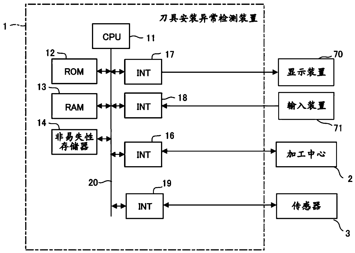
[0025] below, with Figure 1 Embodiments of the present invention will be described below.

[0026] figure 1 It is a schematic hardware configuration diagram showing main parts of the device for detecting abnormality in tool mounting (tool mounting abnormality detection device, ie, device 1 ) including the machine learning device of the first embodiment. The device 1 of the present embodiment can be mounted, for example, on a control device that controls the machining center 2 . In addition, the device 1 of the present embodiment can be implemented as a personal computer installed side by side with a control device for controlling a machining center, an edge computer connected to the control device via a wired / wireless network, a cell computer, a host computer, a cloud server, or other computers. . In this embodiment, an example of the case where the device 1 is installed as a personal computer installed in parallel with a control device for controlling the machining center...


PUM


Abstract

The invention provides a device for detecting abnormality in attachment of tool. The tool attachment abnormality detection device acquires data associated with a machining center, performs pre-processing to create data regarding at least chronological data of a vibration or sound that has been generated in a tool change when a tool has been attached to a tool magazine, where the data is created based on the data that has been acquired, and detects an abnormality in attachment of the tool to the tool magazine based on the data created in the pre-processing stage.

Description

technical field [0001] The present invention relates to a device for detecting an abnormality in the mounting of a tool. Background technique [0002] In the field of machine tools, machine tools with automatic tool changers, in particular so-called machining centers, are widely used. A typical machining center has a tool magazine that holds a plurality of tools each mounted to a tool holder. The machining center selects a specified tool and moves it to a specified position through the distribution operation of the tool magazine, and removes each tool holder from the tool magazine and inserts it into the spindle through the tool replacement operation of the tool changing robot arm. They are combined and used in processing (for example, International Publication No. 93 / 18884, that is, Japanese Patent Application Laid-Open No. 05-261638 (Patent Document 1)). [0003] As an example of the prior art for detecting such an abnormality in the tool replacement operation, in the ab...

Claims


Application Information

Patent Timeline
Patent Type & Authority Applications(China)
IPC IPC(8): B23Q3/155B23Q17/00
CPCB23Q3/155B23Q17/00B23Q17/098B23Q17/12G05B19/4065G05B23/0227G05B2219/37244G05B2219/37351
Inventor 中滨泰广
Owner FANUC LTD
Why Eureka
Try Eureka