Special rubber processing equipment

A special equipment, rubber technology, applied in metal processing and other directions, can solve the problems of cumbersome operation, low cutting efficiency, low practicability, etc., to achieve the effect of simple operation, improved flexibility, and improved work efficiency

Active Publication Date: 2020-05-22
四川道弘新材料有限公司
View PDF6 Cites 6 Cited by
  • Summary
  • Abstract
  • Description
  • Claims
  • Application Information

AI Technical Summary

Problems solved by technology

[0003] The existing rubber strip cutting machine is made of a single piece. A piece of rubber needs to be manually cut many times to cut out all the rubber strips of the required size. It is impossible to cut the whole piece of rubber into multiple strips of the required size at one time. The strip efficiency is low, and the cutting blade of the traditional rubber strip cutting machine is fixed, and the width cannot be adjusted, so that it cannot change the strip width after the rubber is cut, and the practicability is low. Disassembly for grinding, cumbersome operation

Method used


Image

  • Special rubber processing equipment
  • Special rubber processing equipment
  • Special rubber processing equipment

Examples


Embodiment 1

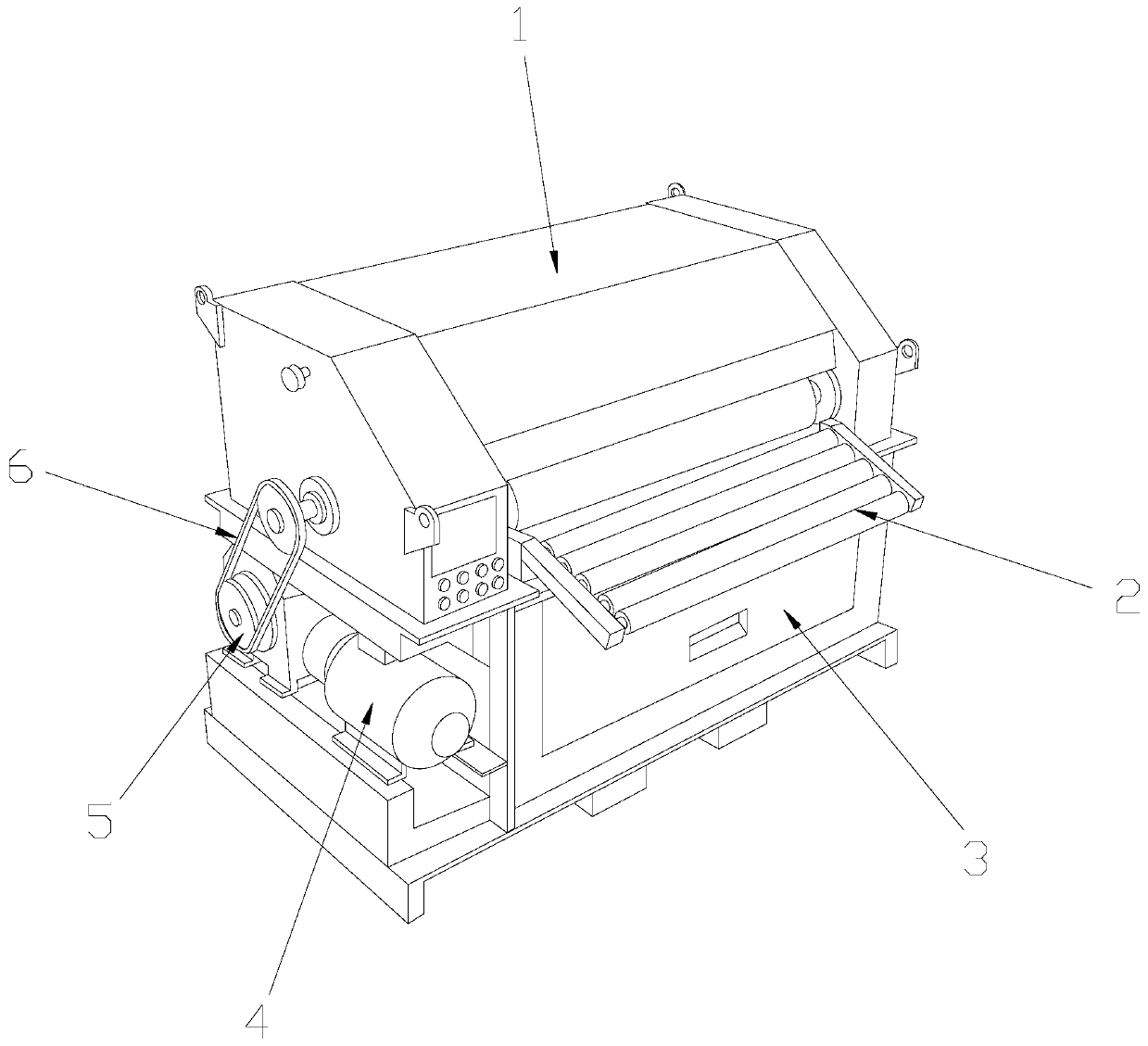
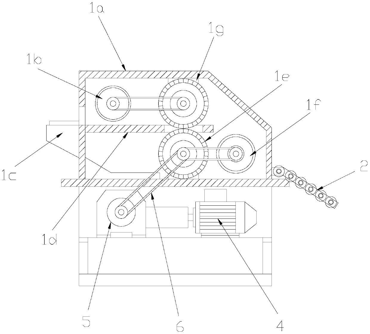
[0034] see Figure 1-Figure 5, the present invention provides a special equipment for rubber processing, the structure of which includes a rubber cloth cutting machine 1, a drum catcher 2, a waste recycling box 3, an engine 4, a gearbox 5, and a transmission chain 6. The rubber cloth cutting A roller catcher 2 is installed on the front end of the strip machine 1, and a waste scrap recycling box 3 is provided on the inner side of the bottom end of the rubber cloth strip cutting machine 1, and the rubber cloth strip cutting machine 1 and the waste scrap recycling box 3 slide In cooperation, the left end of the rubber cloth cutting machine 1 is provided with an engine 4, the rubber cloth cutting machine 1 is connected with the engine 4, a gearbox 5 is installed on one end of the engine 4, and the speed change The box 5 is connected to the upper end of the rubber cloth cutting machine 1 through a transmission chain 6;

[0035] The rubber cloth cutting machine 1 is composed of a b...

Embodiment 2

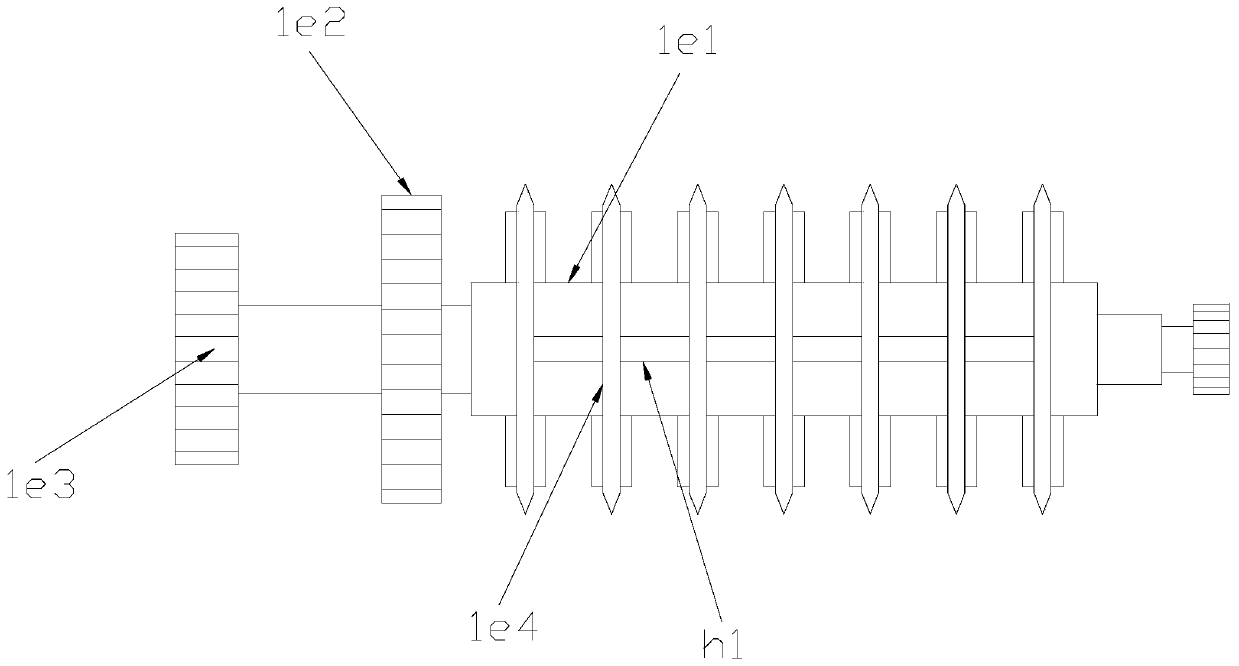
[0044] see Figure 1-Figure 8 , the present invention provides a special equipment for rubber processing. The sharpening mechanism 1g is composed of a mounting bar 1g1, a second rotating cap 1g2, a sharpening frame 1g3, and a blade groove 1g4. The top of the sharpening frame 1g3 is equipped with a Mounting bar 1g1, two or more blade grooves 1g4 are equidistantly distributed under the bottom of the sharpening frame 1g3, a second rotating cap 1g2 is provided on the left end of the sharpening frame 1g3, and the sharpening frame 1g3 and the second rotary cap 1g2 adopt clearance fit.

[0045] The second rotary cap 1g2 also includes a third screw rod 1g21, a second threaded sleeve 1g22, a sharpening block 1g23, a slide rod 1g24, and a ball 1g25, and one end of the second rotary cap 1g2 is provided with a third screw rod 1g21, the second rotating cap 1g2 and the third screw rod 1g21 are welded by electric welding, and more than two second threaded sleeves 1g22 are installed on the s...


PUM


Abstract

The invention discloses special rubber processing equipment. The special rubber processing equipment structurally comprises a rubber canvas strip cutting machine, a roller receiver, a waste chip recovery box, an engine, a gearbox and a transmission chain, wherein the rubber canvas strip cutting machine feeds rubber canvas into a workbench for cutting through guide rollers, a size-adjustable cutting mechanism cuts the rubber canvas into strips at the same time by using a plurality of cutting blades, the rubber canvas is cut into a plurality of strips at a time, the distance among the cutting blades is controlled to be shortened or lengthened through a first rotary cap, the width of the cut rubber canvas strips is changed, the working flexibility is improved, the cutting blades press the rubber canvas through an auxiliary abutting plates, the rubber canvas is prevented from shaking to affect the strip cutting effect during strip cutting, the cutting blades are automatically ground by using a grindstone, the working efficiency is improved, operation is easy, according to the design, the cutting blades do not need to be detached for the grinding, and manual grinding is also not needed.

Description

technical field [0001] The invention relates to the field of rubber processing equipment, in particular to a special equipment for rubber processing. Background technique [0002] Rubber strip cutting machine is a commonly used mechanical device. Its main function is to help users quickly complete rubber cutting. The cutting efficiency is more than ten times that of manual labor. Such a high-efficiency rubber cutting machine is specially made for rubber production enterprises. The production of the rubber cutting machine saves a lot of labor costs and greatly improves the cutting efficiency. [0003] The existing rubber strip cutting machine is made of a single piece. A piece of rubber needs to be manually cut many times to cut out all the rubber strips of the required size. It is impossible to cut the whole piece of rubber into multiple strips of the required size at one time. The strip efficiency is low, and the cutting blade of the traditional rubber strip cutting machin...

Claims


Application Information

Patent Timeline
Patent Type & Authority Applications(China)
IPC IPC(8): B26D7/06B26D7/26B26D7/02B26D7/12B26D1/147
CPCB26D1/147B26D7/025B26D7/06B26D7/12B26D7/2621B26D7/2635Y02P70/10
Inventor 钱炳祥
Owner 四川道弘新材料有限公司
Why Eureka
Try Eureka